Speedway Revolution Installation and Operations Guide Octane 4.8
Chapter 2: Installing and Connecting
Copyright © 2011, Impinj, Inc.
7
Chapter 2: Installing and Connecting Speedway
Revolution
This chapter provides details about the Speedway Revolution I/O ports and status LEDs, and
explains how to install the reader and connect it to your network.
Speedway Revolution Ports and LEDs
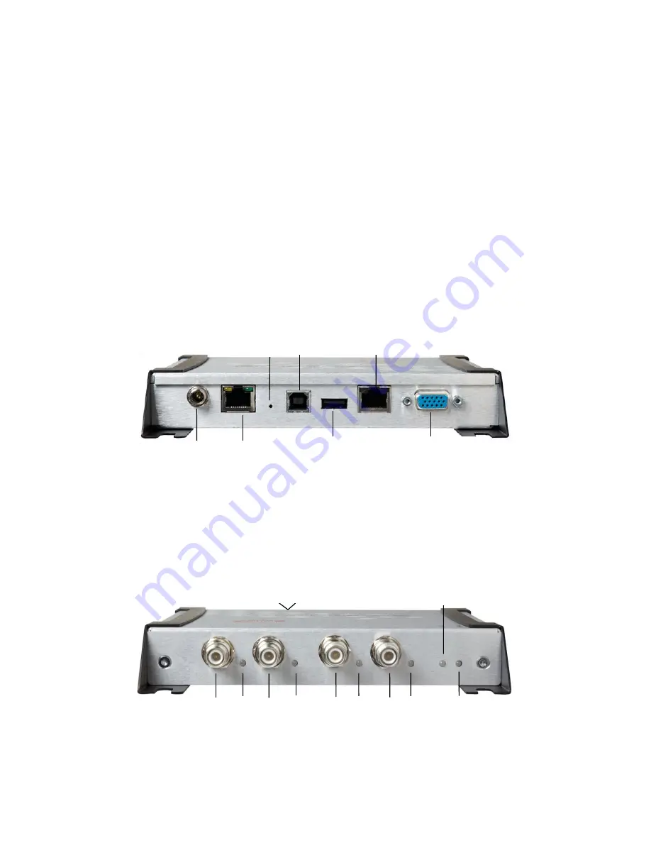
The following graphic illustrates the I/O ports located on the Speedway Revolution Reader.
This graphic illustrates a Speedway R420, which includes four antenna ports visible in Figure
2.2.
Note
: Both Speedway R420 and R220 models have the same exterior ports with one
exception; the R220 includes two antenna ports and the Speedway R420 includes four
antenna ports.
Figure 2.1 Speedway Revolution R420 Port Connections
Note
: See Appendix B:
GPIO Details
for functional and electrical specifications and
details for each pin of the GPIO DE-15 connectors on page 47.
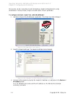
Antenna ports and LED status indicators are located on the back panel of the reader. The
Speedway R420 graphic below illustrates their locations:
Figure 2.2 Speedway Revolution R420 Antenna Ports and Status LEDs
Default Restore
button
USB (Full
Speed) Device
Console
RJ-45 connector
(RS-232)
USB (Full
Speed) Host
+24Vdc locking
connector powered
via external power
10/100 base-T Ethernet
(Power over Ethernet)
GPIO DE-15
4 inputs, 4 outputs
with serial RS-232
Four RP-TCN RF antenna connectors (R420)
(R220 has two antenna connectors)
Reader
Status LED
Antenna 4 and
its status LED
Antenna 3 and
its status LED
Antenna 2 and
its status LED
Antenna 1 and
its status LED
Power status
LED


