background image


ISC300-0-0-GB-03 

November 2009 

Page 2 


Power Input Protection

 ............... 


Over-voltage and over-current protection are 
provided on the Main Power Input. 

NOTE:   

EMC emissions only apply when using the main Power Input Port. 

NOTE:      As an alternative to a battery, power the IXP220 using a 12 V DC 

uninterrupted power supply connected using the Battery Input. 

NOTE:  

The Power Output Port provides a nominal 12 to 14 V DC at 1 A continuous 
current.  When using the 12 V Backup Battery, the output provides up to 3 A 
briefly to cater for in rush currents into locks and other equipment.  When 
using the Controller without the 12 V Backup Battery, then any load that 
demands more than 3 A from the Power Output Port can cause the IXP220 
to protect against overload.  The Controller achieves this by indefinitely 
entering Total Shutdown Mode.  Once the overload is removed, the IXP220 
resumes normal operation after a maximum of 3 seconds. 

Power Supply Combo (IPS96X) 

NOTE:     An integrated transformer supplies power to this model IXP220 Controller.  

The Typical Current Distribution (page 1) for the Open Frame Construction 
applies. 

Transformer 


Input Voltage ..........................  

230 V AC (nominal) at 50 Hz to 60 Hz. 


Output Voltage .......................  

16 V AC. 

Output Current .......................  

2 A maximum. 

The following specifications are common to both the Open Frame Construction and the 
Power Supply Combo options. 

Battery 


Type .......................................  

12 V Sealed Lead Acid, 7 Ahr (Max). 


Approximate Length ...............  

151 mm (6 in) (Max). 


Approximate Width .................  

65 mm (3 in) (Max). 


Approximate Height ................  

99 mm (4 in) (Including the Terminals) (Max). 

Charge Voltage ......................  

13.8 V DC at 350 mA (Max). 

Real Time Clock (RTC) Backup 
Battery 


Battery Type ...........................  

1 x 3 V, CR2032, Lithium cell Battery. 


Battery Life .............................  

2 Years with power OFF, 
5 years with Power ON, 
5 Years Storage with Battery Tab in place. 

Controller Communication  

USB Port

 ....................................... 


USB Device, Type-B, female connector,        
12 Mbps, USB V2.0. 

Ethernet Port

 ................................ 


Standard Ethernet RJ45 connector. 
10/100 Base T, half or full duplex. 


Summary of Contents for GSM900-0-6-GB-XX

Page 1: ...onment similar to IP20 The Power Supply Combo is NOT sealed against water Power Open Frame Construction ISC96X Power Input Main Power Input Port 18 V DC to 32 V DC or 16 V AC to 24 V AC Battery Input...

Page 2: ...the IXP220 resumes normal operation after a maximum of 3 seconds Power Supply Combo IPS96X NOTE An integrated transformer supplies power to this model IXP220 Controller The Typical Current Distributi...

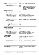
Page 3: ...0 MHz and 1900 MHz Power Consumption Minimum 0 05 W Operating 1 5 W Peak 7 5 W Terminal Communication RS485 Terminal Port Electrical Interface RS485 Baud Rate 38 400 Data Format 8 data bits no parity...

Page 4: ...n other words the Controller distinguishes between tampering on the circuit and the door being in an actual Normally Open or Normally Closed state By placing Resistors into the circuit between the Rea...

Page 5: ...LED Steady Red LED internally visible Incoming RS485 Data Flashing Green LED internally visible Outgoing RS485 Data Flashing Red LED internally visible Incoming RS232 Data Flashing Green LED internal...

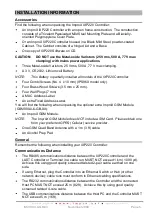
Page 6: ...Label An extra Fixed Address Label You will find the following when unpacking the optional extra ImproX GSM Module GSM900 0 6 GB XX An ImproX GSM Module NOTE The ImproX GSM Module does NOT include a...

Page 7: ...ndividual conductor cross sectional area should not be less than 0 2 mm 2 0 0003 in 2 Ensure that your cable specifications are similar to the following Conductor Resistance 2 ohms Capacitance Core to...

Page 8: ...he removable Battery Tab underneath the Controller s Cover Plate in line with the Impro logo on the right hand side 4 Pull the removable Battery Tab out of the Battery Holder 5 Apply power to the Cont...

Page 9: ...onnect the ImproX GSM Module BEFORE powering up the IXP220 Controller Power down the IXP220 Controller BEFORE removing the GSM Module 1 Insert the SIM Card as shown on the Module 2 Access the IXP220 C...

Page 10: ...ase to the wall using two of the supplied screws in the Mounting Key Holes 2 Fix the third screw in the Mounting Slot adjusting the position of the Base if necessary DIP switch Settings NOTE Once the...

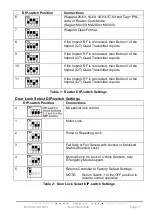
Page 11: ...utton 3 of the ImproX QT Quad Transmitter reports 11 If the ImproX RF is connected then Button 4 of the ImproX QT Quad Transmitter reports Table 1 Reader DIP switch Settings Door Lock Select DIP switc...

Page 12: ...ISC300 0 0 GB 03 November 2009 Page 12 ELECTRICAL CONNECTIONS IXP220 Controller Key Component Positions Figure 4 Key Component Positions...

Page 13: ...ISC300 0 0 GB 03 November 2009 Page 13 Power Supply Combo IPS96X Key Component Positions Figure 5 Power Supply Combo Layout...

Page 14: ...ISC300 0 0 GB 03 November 2009 Page 14 Electrical Connections Figure 6 IXP220 Controller Left hand Side Connection Details...

Page 15: ...ISC300 0 0 GB 03 November 2009 Page 15 Figure 7 IXP220 Controller Right hand Side Connection Details...

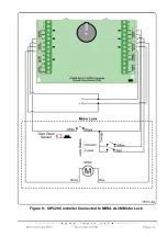
Page 16: ...ISC300 0 0 GB 03 November 2009 Page 16 Figure 8 IXP220 Controller Connected to MIWA AL3M Motor Lock...

Page 17: ...ISC300 0 0 GB 03 November 2009 Page 17 Figure 9 IXP220 Controller Connected to a Pulse or Solenoid Lock...

Page 18: ...Power Control Lockdown Mode This Mode allows you to lockdown all Doors Locations on a single Controller That is essentially denying Tagholder entry Where you have 2 Controllers with inter controller...

Page 19: ...installed Alarm Panel and a simple Alarm Sensor is required You may connect Passive Infrared or other types of sensors to the IXP220 System s Digital Inputs Inputs 1 and 2 If any of these sensors tri...

Page 20: ...utton In this mode the Bell Button on the ImproX KMA Mullion Keypad Antenna Reader when pushed drives Relay 3 on the IXP220 Controller Action Mode Use this Mode to drive Relay 3 when using the Buildin...

Page 21: ...Combo see Figure 14 Using the supplied Quick Click Glands or Gland Breakouts neatly lead the wires out of the Cabinet Wiring the Mains Input Power Cord WARNING DO NOT TOUCH ANY PART OF THE CIRCUIT ONC...

Page 22: ...re replacing the fuse 1 Disconnect the mains power supply 2 Open the Cabinet 3 Disconnect the Positive Lead from the Battery 4 Unscrew the Fuse Cap 5 Remove the old fuse from the Fuse Cap 6 Insert the...

Page 23: ...ils 5 Reattach the Controller s Cover Plate UNIT ADDRESS IMFORMATION Fixed Address Once the IXP220 Controller is installed sketch a rough site plan Attach the loose additional Fixed Address Label pack...

Page 24: ...he extra loose MAC Address Label alongside the Fixed Address Label to the Unit Location Chart enclosed or your sketched site plan IP Address NOTE All ImproX IXP220 Controllers have the same IP Address...

Page 25: ...ISC300 0 0 GB 03 November 2009 Page 25 Fixed Address Label Unique Location Description...

Page 26: ...ISC300 0 0 GB 03 November 2009 Page 26 Fixed Address Label Unique Location Description...

Page 27: ...ISC300 0 0 GB 03 November 2009 Page 27 Fixed Address Label Unique Location Description...

Page 28: ...ISC300 0 0 GB 03 November 2009 Page 28 Fixed Address Label Unique Location Description...

Page 29: ...ISC300 0 0 GB 03 November 2009 Page 29 Fixed Address Label Unique Location Description...

Page 30: ...ISC300 0 0 GB 03 November 2009 Page 30 Fixed Address Label Unique Location Description...

Page 31: ...ISC300 0 0 GB 03 November 2009 Page 31 Fixed Address Label Unique Location Description...

Page 32: ...on Chart GUARANTEE OR WARRANTY CAUTION We reserve the right to nullify the products guarantee or warranty where you have not properly installed the Metal oxide Varistors This product conforms to our G...

Page 33: ...ISC300 0 0 GB 03 November 2009 Page 33 USER NOTES...

Page 34: ...ISC300 0 0 GB 03 November 2009 Page 34 USER NOTES...

Page 35: ...ISC300 0 0 GB 03 November 2009 Page 35 USER NOTES...

Page 36: ...62 1 0 GB 01 IPS960 1 0 GB 02 IPS961 1 0 GB 02 IPS962 1 0 GB 02 and IPS9631 0 GB 02 and the ImproX GSM Module GSM900 0 6 GB 00 The last two digits of the Impro stock code indicate the issue status of...

Reviews: