background image

Digital Inputs 
General 

Type 

 ............................................. 


2 Dry-contact inputs with End-of-line (EOL) 

Sensing and 2 Dry-contact inputs without End-

of-line (EOL) Sensing. 

Detection Resistance Range

 ...... 


< 2 kOhm. 

Protection Range

 ......................... 


+15 V continuous. 


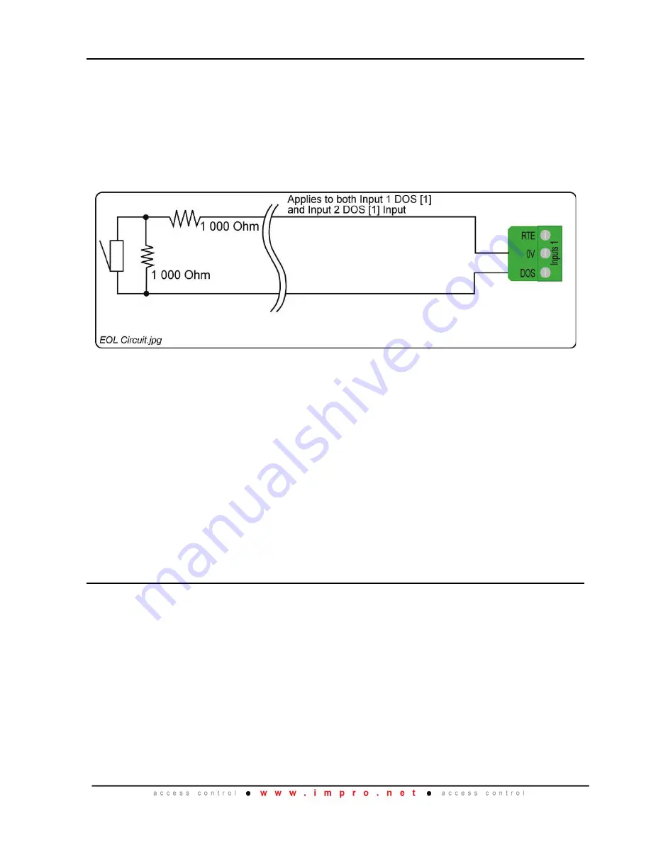
Figure 1:  End-of-line (EOL) Sensing Circuit 

NOTE: 

End-of-line (EOL) Sensing enables the WRM to raise an alarm when 

somebody tampers with the circuit (cutting or shorting the wires) between 

either Reader 1 Inputs [1] DOS or Reader 2 Inputs [2] DOS and GROUND 

(GND).  In other words the Module distinguishes between tampering on the 

circuit, and the door being in an actual ‘Normally Open’ state.   


By placing Resistors into the circuit between either Reader 1 Inputs DOS [1] 

or Reader 2 Inputs DOS [1] and GROUND (GND), the Module’s Digital Input 

monitors a constant resistance through the circuit.  When the circuit is 

tampered with, the Resistors are bypassed; the Module detects the 

resistance change and raises an alarm. 

 
LED Status and Diagnostic Indicators 

Status LED (RED) 


Supply Voltage Status ............   Off when supply voltage is too high, or too low 


Upgrade Mode .......................   Flashing at a steady rate during upgrade 


Communications Failure ........   Two brief flashes, repeating 

Data LED (GREEN)  

Flashing Green during communication 

Digital Inputs  (1-4)

 ...................... 


Continuous Green on detected contact closure 

Relays (1 and 2)

 ........................... 


Continuous Red on activation of the Relay 


HMW300-0-0-GB-00 

October 2013 

Page 3 


Summary of Contents for HMW700-0-0-NN-XX

Page 1: ...odating legacy hardware and software suites Working Environment Plastic Housing HMW700 Designed to work in an indoor dry environment similar to IP20 The Module is not sealed against water PCB Card for...

Page 2: ...S Bus See WRM Address Information on page 17 for Address usage with one Reader connected Reader Options Reader 1 Wiegand and Reader 2 Wiegand allow connection to the following hardware Impro MDR Mult...

Page 3: ...ly Open state By placing Resistors into the circuit between either Reader 1 Inputs DOS 1 or Reader 2 Inputs DOS 1 and GROUND GND the Module s Digital Input monitors a constant resistance through the c...

Page 4: ...hrough the cover of the housing Five Ziploc bags containing the following Four Stand Offs for spacing the WRM away from the mounting surface and two Cluster Connector Covers for closing off the cluste...

Page 5: ...when it would be convenient to install a WRM some distance from its Cluster Controller The following applies The maximum S Bus Cable length from the Cluster Controller to the WRM is 150 m 490 ft A max...

Page 6: ...de Remote The maximum cable distance between the Impro WRM and its Multi mode Remote MUST NOT exceed 10 m 33 ft Achieve this by using good quality screened twisted pair cable Distance between Reader U...

Page 7: ...st its neighbouring Module mark the mounting hole locations through the mounting holes in the back of the Housing Base Remove the WRM drill the mounting holes Use the plastic Stand Offs to provide spa...

Page 8: ...ng surface using fasteners not included appropriate for the mounting surface material Select the gland plates that best suit the installation and or knock out the cable entry points as needed Connect...

Page 9: ...PIN code or Reason Code Mode Sagem MA100 MA200 MA300 or Sagem J Series 8 Wiegand open format 9 LEGACY UHF Receiver Support If the UHF Receiver is connected then Button 1 of the Quad Transmitter repor...

Page 10: ...de in Tag PIN Reason Mode If the Impro WRM expects a PIN code and receives a number greater than 65535 then the WRM assumes the number to be a tag code The WRM discards the previously read Tag for the...

Page 11: ...ELECTRICAL CONNECTIONS Key Component Positions Figure 3 Impro WRM Key Component Positions HMW300 0 0 GB 00 October 2013 Page 11...

Page 12: ...Figure 2 for Arc Suppression details NOTE The ideal cable distance between the Impro WRM and its Multi discipline Reader MUST NOT exceed 150 m 164 yd NOTE This diagram shows typical connections to th...

Page 13: ...Reader WKM900 or the Wiegand Junction Box Reader WJB900 use the cable colours displayed in brackets NOTE Connection details remain the same for all Wiegand models NOTE Use the connections shown here...

Page 14: ...WRM Connected to a Multi mode Remote NOTE Connection details remain the same for all Multi mode Remote models NOTE The cable distance between the Impro WRM and its Multi mode Remote MUST NOT exceed 1...

Page 15: ...Connecting other Devices Figure 7 Connecting other Devices to the WRM HMW300 0 0 GB 00 October 2013 Page 15...

Page 16: ...mpro WRM and its relay driven loads in an unclustered remote installation position Figure 8 Typical S Bus and Power Wiring for Remote Installation NOTE The wiring of the RTE DOS and Reader Terminals r...

Page 17: ...witches off and no MDR is connected to one channel the fixed address for the un used channel will be hidden In all other instances both addresses on the WRM are always shown Fixed Address Label Once t...

Page 18: ...USER NOTES HMW300 0 0 GB 00 October 2013 Page 18...

Page 19: ...USER NOTES HMW300 0 0 GB 00 October 2013 Page 19...

Page 20: ...and HMW701 0 0 GB 00 The last two digits of the Impro stock code indicate the issue status of the product HMW300 0 0 GB 00 Issue 01 October 2013 Impro Access Portal WRM Wiegand Reader Module English...

Reviews: