XTT301-0-0-GB-15
December 2010
Page 3
XTT909
Ten ImproX CA Antenna Reader printed circuit board assemblies.
An extra Serial Number Label.
XTT950
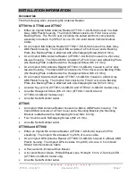
An ImproX Antenna Junction Box Reader housed in a Black, ABS Plastic housing.
The Antenna Reader consists of a Front Cover and a Backing Plate Assembly (the
Front Cover is attached with a Combi Screw (6 mm x 2.2 mm)). The Backing Plate
Assembly includes 1 m (3.28 ft) of 10-core, 6.2 mm cable.
An extra Serial Number Label.
General
Remember the following when installing the Antenna Reader:
Antenna Reader Distance
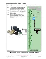
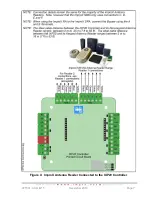
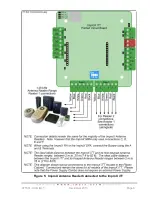
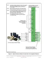
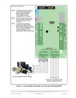
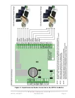
The ideal cable distance between the Terminal, Controller or Receiver and its Antenna
Reader ranges between 2 m to 16 m (7 ft to 53 ft).
NOTE:
When used with the ImproX iTT or the IXP20 Controller (iTT Platform) the
ideal cable distance between the Terminal or Controller and Non-keypad
Antenna Readers ranges between 2 m to 25 m (7 ft to 82 ft). The ideal
cable distance between the Terminal or Controller and Keypad Antenna
Readers ranges between 2 m to 16 m (7 ft to 53 ft).
Optimal performance is not guaranteed outside of the range. Achieve optimal
performance by using a good quality shielded multi-strand 3-pair twisted cable. The
cross-sectional area of the cable must not be less than 0.2 mm
2
(0.0003 in
2
).
Cable Specifications
The cable specifications should be similar to the following:
Conductor Resistance:
< 2 ohms.
Capacitance, Core to Earth:
< 160 pF/m.
Capacitance, Core to Core:
< 100 pF/m.
Distance between Antenna Readers from the SAME Terminal, Controller
or Receiver
To avoid mutual interference, install the Antenna Readers no closer than 150 mm (6 in)
apart.
Distance between Antenna Readers from DIFFERENT Terminals,
Controllers or Receivers
To avoid mutual interference, install the Antenna Readers no closer than 500 mm
(20 in) apart.
Mounting the Antenna Readers
CAUTION:
Make certain that you mount the Antenna Reader on a vibration-free
surface.


