


XTT309-0-0-GB-04
December 2007
Page 3
Mounting the ImproX CA
WARNING: DO NOT MOUNT THE IMPROX CA IN THE SAME ELECTRICAL
JUNCTION BOX AS THE MAINS ELECTRICAL SUPPLY.
CAUTION:
Make certain that you mount the Antenna Reader on a vibration-free
surface.
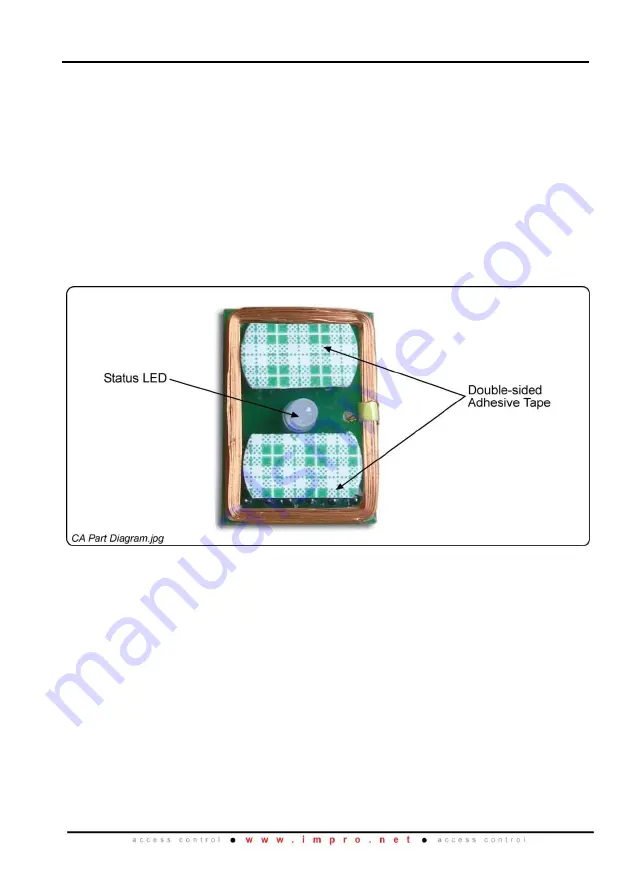
1.
Drill a 5 mm hole in the centre of your chosen Electrical Conduit Blanking Plate, to
accommodate the Status LED.
2.
Remove the paper covering from the double-sided adhesive tape.
NOTE:
Place general purpose Silicone Sealer around the base of the Status LED
for added waterproofing.
3.
Push the Status LED through the hole, in the Blanking Plate, from back to front.
4.
Firmly press the ImproX CA to the back of the Electrical Conduit Blanking Plate.
Figure 2: ImproX CA Part Diagram
Blank Space


