© Copyright 2010 IMS Company. All rights reserved.
An ISO 9001:2008 Registered Quality Company
7
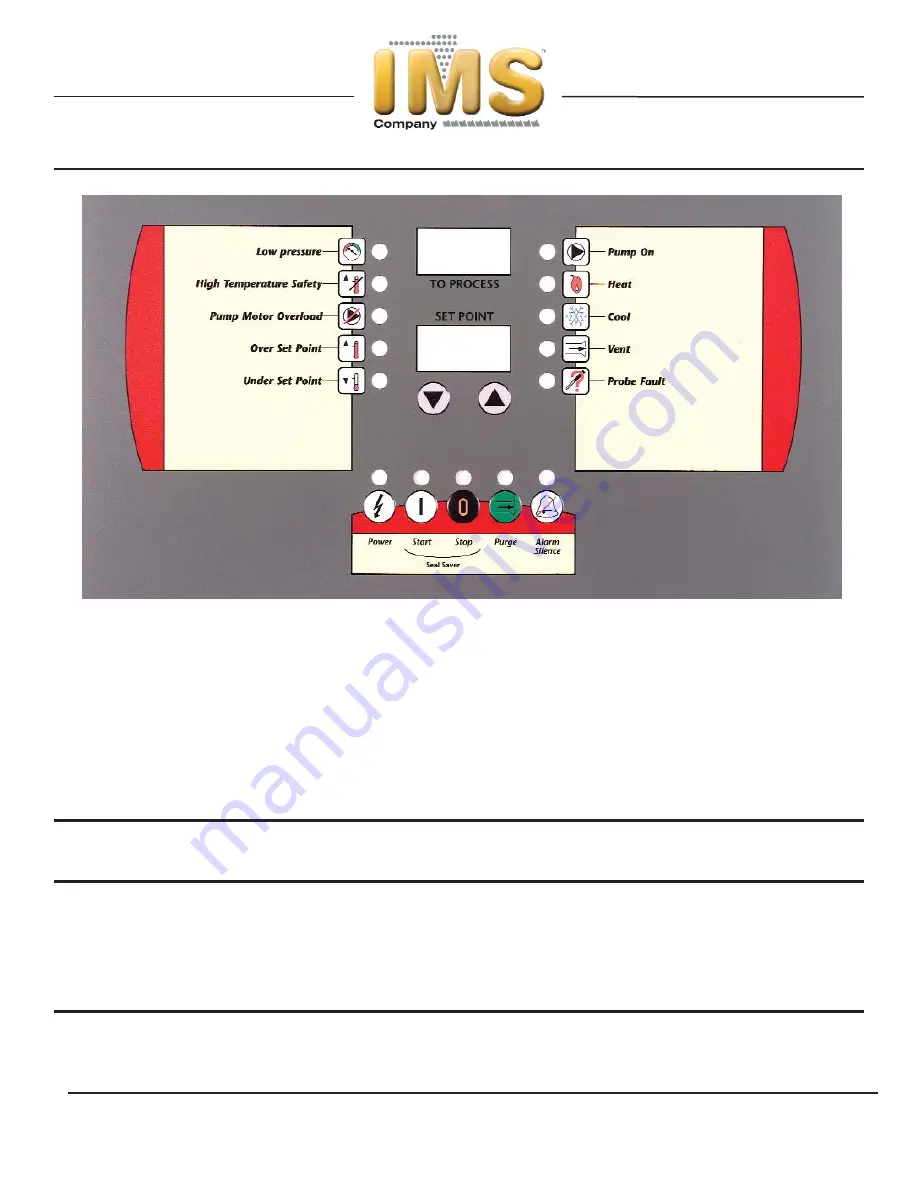
Control Panel Operation
The temperature control unit includes a microprocessor controller designed to perform all control functions directly from the front
panel. When a button is pressed, a click will be felt and the
corresponding LED will be energized.
The table shown below provides the basic control fault logic for the microprocessor controller.
Table 2 - Microprocessor Control Fault Logic
Alarm
Manual
Remote
Fault
Alarm
Pump Shut
Heater Shut
Unit Shut
Reset
Reset
Alarm
Indication Off
Off
Off
Required
1
Required
2
Activated
3
Low Pressure
LED
Yes
Yes
Yes
No
No
Yes
High Temperature Safety
LED
Yes
Yes
Yes
Yes
No
Yes
Pump Motor Overload
LED
Yes
Yes
Yes
Yes
Yes
Yes
Over Set Point
LED
No
No
No
No
No
Yes
Under Set Point
LED
No
No
No
No
No
Yes
Probe Fault
LED
Yes
Yes
Yes
Yes
No
Yes
Low Power
Pr OFF
Yes
Yes
Yes
Yes
No
Yes
1 Alarm Reset button or Stop button on control panel must be pressed.
2 Safety control must be manually reset before the controller can be reset.
3 Activates the alarm horn (if included) and closes the alarm contact (if included).


