12/89:
PARTS-75
OVERLOAD SHUTDOWN INSTALL INSTRUCTIONS
(99903341-4)
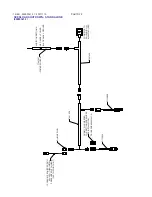
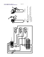
Notes:
1. Set pressure switches to the initial setting indicated per
crane model. (see chart)
2. Before proceeding further, make sure all overload shut-
down components are installed.
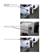
3. Install correct pressure switch (using chart) insto the inner
and the outer cylinders.
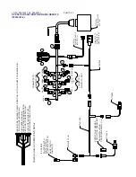
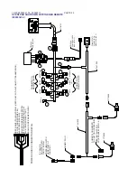
4. Install inner cylinder pressure switch and plug it into the
harness as indicated on drawings 99903341-1 through 3.
5. Install dummy plug (supplied with harness) into outer
cylinder pressure switch location.
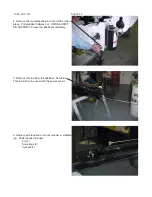
6. With a rated load attached, (using capacity chart, find the
load where the extension booms extend to approximately
mid-stroke (keeping the extension booms in a horizontal
position.)) With the crane rotated to a position where the unit
is stable, set the inner boom at approximately 15° above
horizontal and the outer boom at the horizontal position.
(Keep extension booms retracted.)
7. Now extend the extension booms out until the overload activates. Check to see that neither the inner or outer boom
cylinders are drifting. If booms are drifting, decrease the setting on the inner boom pressure switch until the drifting
stops. Continue extending booms until inner boom does not drift. Double check the capacity chart length with the
crane to see that the load is correct for the crane. If not, adjust pressure accordingly .
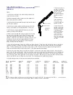
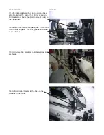
8. Remove the outer boom dummy plug from the harness. Connect the outer boom pressure switch. Raise the inner
boom to 45 - 50° above horizont al. raise the outer boom to the same angle (see the crane angle det ail.) Starting with
the extension booms fully retracted, extend the booms until the crane goes into overload. The outer boom should not
drift. If the outer boom drifts, adjust the outer boom pressure switch. Repeat the procedure. Double check the capacity
chart to see that the crane is lif ting the correct load. If not, adjust pressure switched accordingly .
9. Tighten locking screws on both inner and outer pressure switches.
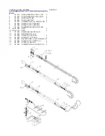
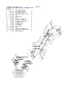
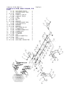
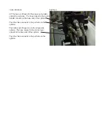
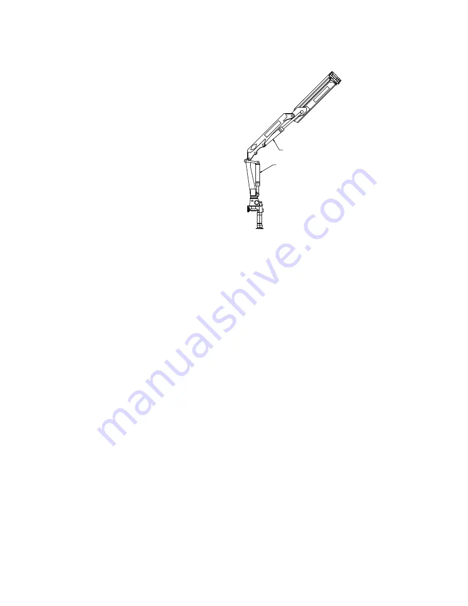
OUTER CYLINDER
INNER CYLINDER
CRANE ANGLE
(NOTE #8)
SCALE 1:10
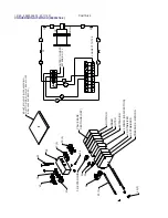
The system operates by
sending 12 volts to the
dump solenoid. If at any
time the crane loses 12
volts or goes into
overload, the following
functions are inoper-
able:
•
Extension boom out
•
Inner boom down
•
Outer boom down
All other functions will
operate correctly.
The pressure switch
settings must be lower
than the cylinder load
holding valve settings.
This will allow the
pressure switches to
open up before the
crane load holding
valves, and will not
allow the crane booms
to lower in an overload
condition.
CRANE MAIN RELIEF
INNER CYL
INNER CYL
OUTER CYL
OUTER CYL
INNER CYL
OUTER CYL
MODEL PSI
R/V PSI
C/B PSI
R/V PSI
C/B (PSI)
SWITCH (PSI)
SWITCH (PSI)
4/29
3842
3842
4277
3842
4350
4100
4000
5/35
3842
3842
4277
3842
4350
4100
4000
6/45
3842
3842
4277
3842
4350
4100
4000
7/51
4060
4350
4423
3915
3988
4200
3600
9/63
4568
4713
4931
3988
3988
4750
3600
11/76
3843
NONE
4205
3988
4350
4000
4000
12/89
3843
NONE
4350
3988
3988
4150
3600
15/113
4060
NONE
5075
4350
4570
4850
4200
16/117
3915
NONE
5075
4350
4495
4850
4200
NOTE:
This chart indicated setting for initial pressure switch starting points, except for the 12/89. The pressures for the 12/89 ar
e actual pressure
settings. All cranes need to be tested for proper setting of pressure switches at the time of installation.
99903341.04: 20011115
Summary of Contents for 12/89
Page 91: ...12 89 PARTS 91...

