7
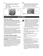
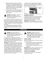
1. Be sure that all safety measures required by the
equipment manufacturer have been followed. (i.e.
crane level, stabilizers down, etc.)
2. Push in the transmitter E-stop pushbutton.
3. Switch the transmitter "ON". A short buzzer signal
will sound.
4. Wait for the second buzzer signal (approx. 3
seconds).
5. The green LED on the transmitter control panel
will flash.This indicates that the transmitter is
working and is ready to use.
6. Pull out the E-stop pushbutton.
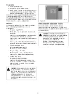
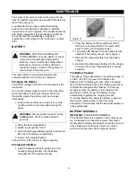
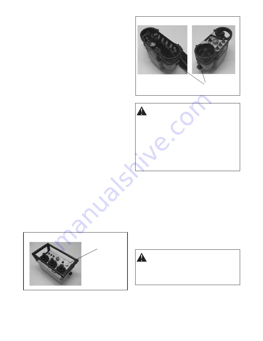
7. Push the green pushbutton "Start/horn" on the
transmitter.
8. Check that the machine functions correspond
with the transmitter functions.
IMPORTANT:
The machine functions will operate
during this check. Be certain that there are no
obstacles near the machine.
9. Push the "EMERGENCY STOP" pushbutton on
the transmitter. Be sure that no functions can be
activated with the "EMERGENCY STOP"
pushbutton depressed.
IMPORTANT:
If any function of the radio remote
control activates with the "EMERGENCY STOP"
engaged, the radio remote control must not be used
until it is repaired.
10. Pull out the "EMERGENCY STOP" pushbutton.
11. Push the green pushbutton "Start/horn" on the
transmitter.
12. Both the radio remote control and the machine
are now ready for operation.
IMPORTANT:
To avoid accidental start-up, always
engage the E-stop pushbutton and switch the
transmitter "OFF" when not in use. When the
transmitter is not attached to the operator, the key
switch should be removed and stored in a secure
place.
SPEED CONTROL
This radio remote control system is equipped with a
dual range speed control. The switch allows selection
between high range (rabbit) and low range (snail). The
low range provides <70% of full speed.
PROPORTIONAL FUNCTIONS
The proportional functions and speed ranges are
pre-set by
IMT
according to the valve types. Your
dealer can refer to the basic adjustments at any time.
Only the crane manufacturer, dealer or authorized
service representative is allowed to adjust individual
functions, direction and speed range.
OPTICAL DISPLAYS AND ACOUSTIC
SIGNALS
The radio remote control system uses optical displays
and acoustic signals to show current working status.
GL-2
GL2_0020
Start
Pushbutton
Figure 8
WARNING:
TO AVOID SERIOUS INJURY
OR DEATH. Switch the machine "OFF" if
there is a fault or any problems with the safety
check. Contact
IMT
or your dealer
immediately to repair the system. NEVER
operate the machine when the
"EMERGENCY STOP" function does not
operate properly.
Improper operation, maintenance or
adjustment may cause serious injury or
damage to equipment and may void the
warranty.
CAUTION:
DO NOT OPEN THE RECEIVER.
All relay and proportional outputs are
accessible on the connection plug.
Unauthorized entry into the receiver could
result in damage to equipment and may void
the warranty.
Nova-L
NVL_0010
NVL_0020
Start
Pushbuttons
Figure 9
Summary of Contents for 16000-SIII
Page 13: ......

