14
IMT 2003i Technical Specifications & Parts Manual # 99904385
Crane Capacity
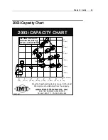
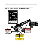
The IMT crane is designed to lift specific loads. These loads are defined on the capacity placard
mounted near the operator’s station and on the crane. Exceeding the limits presented on the
capacity placard will create severe safety hazards and will shorten the life of the crane. The
operator and other concerned personnel must know the load capacity of the crane and the
weight of the load being lifted!
The capacity chart for each model is located in the specific crane technical specifications manual
and on placards on the crane and body.
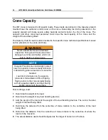
WARNING
Never exceed the crane’s rated load
capacities. Doing so will cause structural
damage to winches and cables which can
lead to death or serious injury.
NOTE
Capacity Placards are intentionally located
near the operator to assure ready reference
in determining when a load can or cannot be
handled.
Load limit information on the capacity
placards is formulated on 85% of tipping.
Tipping refers to the crane actually tipping
with its opposite stabilizer and tires having
broken contact with the surface.
Prior to lifting a load:
1
Determine the weight of the load.
2
Determine the weight of any load handling devices.
3
Add the weight of the load and the weight of the load handling devices. The sum is the total
weight of the load being lifted.
4
Determine the distance from the centerline of crane rotation to the centerline of the load
being lifted.
5
Determine the distance from the centerline of crane rotation to the centerline of where the
load is to be moved to.
6
The actual distance used should be figured as the larger of items 4 and 5 above.
Summary of Contents for 2003i
Page 2: ......
Page 6: ......
Page 38: ......
Page 77: ...Chapter 8 General Reference 75 X R CA ITEM EXPLANATION DATE CORRECTED ...


