background image


74 

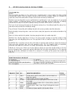
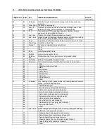
IMT 2003i Technical Specifications & Parts Manual # 99904385 


Deficiency / Recommendation / Corrective 

Action Report 

DATE: 

OWNER: 

UNIT I.D. NUMBER: 


GUIDELINES


A deficiency (X) may constitute a hazard.  Deficiency must be corrected and/or faulty parts 

replaced before resuming operation. 

Recommendations (R) should be considered for corrective actions. Corrective action for a 

particular recommendation depends on the facts in each situation. 

Corrective actions (CA), repairs, adjustments, parts replacement, etc. are to be performed 

by a qualified person in accordance with all manufacturer’s recommendations, 
specifications and requirements. 

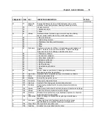
NOTE:  Deficiencies (X) listed must be followed by the corresponding corrective action taken (CA). 

X = DEFICIENCY          R = RECOMMENDATION          CA = CORRECTIVE ACTION TAKEN


X,R,CA  ITEM #  EXPLANATION 

DATE CORRECTED 


Summary of Contents for 2003i

Page 1: ...ttp www imt com Copyright 2017 Iowa Mold Tooling Co Inc All rights reserved No part of this publication may be reproduced stored in a retrieval system or transmitted in any form or by any means electronic mechanical photocopying recording or otherwise without the prior written permission of Iowa Mold Tooling Co Inc Iowa Mold Tooling Co Inc is an Oshkosh Corporation Company ...

Page 2: ......

Page 3: ...ndle Operating Instructions 23 Crane Shut Down 24 Operation in Poor Conditions 25 Hand Signals 25 Maintenance Repair 27 Maintenance Introduction 27 Electric Crane Power Safety 28 Maintenance Schedule 28 Electric Crane Lubrication 29 Grease Zerks 29 Pin Removal Inspection 30 Electric Crane Wear Pads 31 Wire Rope Inspection 32 Wire Rope Lubrication 33 Wire Rope Maintenance 33 Wire Rope Inspection Re...

Page 4: ...Electrical Box Gear Guard 99904352 4 55 Boom Winch Crane Assembly 99904352 5 56 Electrical Installation 99904398 58 Electric Crane Battery Circuit 99904884 59 Winch 71570921 Eff 2 09 60 Winch 71570875 Through 2 09 61 Handle Assembly Tethered Remote 51721683 63 Turntable Gear 71056635 65 Decal Kit 95721546 67 General Reference 69 Inspection Checklist 69 Deficiency Recommendation Corrective Action R...

Page 5: ...D BATTERY CIRCUIT DRAWING 20100615 SPECS CORRECTED ELECTRICAL INSTALLATION REQUIREMENTS 20100812 71570921 ADDED 71570921 WINCH PARTS 20111117 ECN 11628 EDIT STABILIZER WORDING UPDATE DECALS 20131120 99904352 2 ECN 12043 11974 20140909 GREASING INSTRUCTIONS ECN 12264 MOLUB ALLOY 882 WAS MOLUB ALLOY 936 20170313 70392399 CN 519 Updated to new grease info ...

Page 6: ......

Page 7: ...nything other than IMT approved equipment If in doubt contact IMT prior to making modifications DO NOT alter or modify any safety device All safety devices must be inspected tested and maintained in proper working condition Decals regarding crane safety and operation are safety equipment and must be maintained Decals must be kept clean and legible OWNER RESPONSIBILITIES You must maintain and opera...

Page 8: ...es personal injury immediately notify your distributor and IMT Technical Support at IOWA MOLD TOOLING CO INC 500 HWY 18 WEST GARNER IA 50438 641 923 3711 CAUTION A CAUTION is used when there is the very strong possibility of damage to the equipment or premature equipment failure WARNING A WARNING is used when there is the potential for personal injury or death NOTE A NOTE is used to either convey ...

Page 9: ... Instructions 8 Daily Safety Inspection 9 Electrical Hazards 11 Crane Capacity 14 Electric Crane Danger Decal Placement 16 Work Site Planning 18 Stabilizer Operation 19 Ground Support 20 Winch Safety 20 C H A P T E R 2 Safety ...

Page 10: ...ngs Keep three wraps of loadline on winch Operate crane controls slowly and smoothly Know the position of the booms at all times while operating the crane Eliminate swing by positioning the boom tip directly over the center of the load before lifting Do NOT operate in excessive wind speeds Keep load under boom tip Do NOT side load boom drag or swing loads Stow boom and stabilizers before traveling...

Page 11: ... into position before lifting This may sideload the crane or stress the wire rope beyond safe limits Equipment damage may result When using a winch always keep the tip of the extension boom as close to the load as practical This will prevent the load from swinging out of control when using the rotation swing function DANGER DO NOT permit personnel to ride the boom loadline hook or load as this act...

Page 12: ... leaks and blockages 4 Weldments Check visually for damage especially cracks or breaks in welds 5 Cylinders Check for leakage and scored rods 6 Fasteners Check pins sheaves nuts and bolts for breakage excessive wear and tightness 7 Crane Hooks Check for the presence of a safety catch twists cracks or damage 8 Ropes Slings Check for frayed edges broken strands kinks flat spots and end attachments 9...

Page 13: ...r covering and appear to be insulated they are not The vehicle or parts of the vehicle do not need to touch the power line for the vehicle to become energized Electricity will arc across gaps and all overhead wires or cables should be considered hazardous and dangerous Always operate the crane so that no part of the crane or load enters the Danger Zone the minimum clearance distance for a powerlin...

Page 14: ...t 6 10 m of high voltage lines energized up to 35 000 volts and 50 feet 15 24 m of high voltage lines energized up to 50 000 volts or of unknown voltage It is the law The operator can be liable if activities in violation of this law cause injury or property damage Only operate in conditions where the vehicle and equipment can be stabilized Do not set up or operate on soft soil mud snow or other un...

Page 15: ...ay You are safe from electrical shock as long as you do not become a pathway for current to flow to the ground Do not approach the vehicle until a power company representative informs you that the line has been de energized and grounded and that the area is safe 4 In certain circumstances the ground around a charged vehicle or downed power line may be energized The ground becomes charged in concen...

Page 16: ...which can lead to death or serious injury NOTE Capacity Placards are intentionally located near the operator to assure ready reference in determining when a load can or cannot be handled Load limit information on the capacity placards is formulated on 85 of tipping Tipping refers to the crane actually tipping with its opposite stabilizer and tires having broken contact with the surface Prior to li...

Page 17: ...fted and must be deducted from the capacity IOWA MOLD TOOLING CO INC BOX 189 GARNER IA 50438 0189 TEL 641 923 3711 FAX 641 923 2424 70397481 15 30 45 0 CL 1 31 m 2 61 m 3 91 m 4 1 2 m 5 1 5 m 6 1 8 m 7 2 1 m 1 31 m 2 61 m 3 91 m 4 1 2 m 5 1 5 m 6 1 8 m 0 Short Base LIFTING CAPACITY IS 2 000 LB 907 kg AT ALL LOCATIONS ...

Page 18: ...14 4 2m 2 0 6m 4 1 2m 8 2 4m 6 1 8m 70395090 DANGER 70394443 FREE FALLING MANUAL BOOM EXTENSION S WILL CAUSE DEATH OR SERIOUS INJURY To avoid winch unspooling use single line downhaul weight with single line Be sure to install weight below locking collar LOCKING COLLAR DOWNHAUL WEIGHT 71394083 Unplug remote pendant and store in tool box or cab when not in use NOTICE GREASE WEEKLY 703974 11 7039741...

Page 19: ...sulated 70396613 Falling Load Hazard Death or serious injury will result from approaching or contacting a power line Falling loads may injure or kill Fall Hazard Riding on boom hook or loadline may injure or kill Overload Hazard Overloading the crane may injure or kill WARNING Weight of load handling devices are part of the load lifted and must be deducted from the capacity There are two warning d...

Page 20: ... any crane operations near powerlines Position the carrier vehicle so that when the crane is fully extended it can t contact electrically charged lines or apparatus Twenty feet 6 10 meters is the minimum distance that any portion of the crane loadline or load can be to electrical lines carrying up to 35 000 volts Allow 50 feet 15 24 m minimum for powerlines with unknown voltages or with voltages a...

Page 21: ...re are various stabilizer designs available but all require extreme caution in their use See figures for proper stabilizer operation sequence and warnings BACK OF TRUCK BACK OF TRUCK BACK OF TRUCK STABILIZERS CAN PINCH STRIKE OR CRUSH OBJECTS OR PEOPLE MAKE SURE THERE ARE NO OBSTRUCTIONS IN OR NEAR THE STABILIZER PATH WARNING 1 EXTEND STABILIZER ARMS TO THEIR FULL HORIZONTAL OPERATING LIMIT 2 EXTE...

Page 22: ... it is level from the front to the rear Use the power down stabilizer function to level the vehicle from side to side Utilize a signal person if the stabilizers are not in view from the operator s station when extending or lowering the stabilizers Winch Safety 1 DO NOT pull the load block or sheave back so that it makes contact with the boom tip This is two blocking and should be avoided 2 Pay out...

Page 23: ... cool down to ambient temperature See the technical specifications for pump performance charts and operating intervals Prior to lifting a load 1 Find the weight of the load 2 Find the weight of any load handling devices 3 Add the load and load handling device weights The sum is the total weight of the load being lifted 4 Find the distance from the crane rotation centerline to the load centerline 5...

Page 24: ...alt surfaces are relatively thin and cannot withstand the stabilizer loading Concrete can break through and cause instability WARNING Avoid injury or equipment damage Do NOT attempt to handle a load if the stabilizers are unable to make solid contact with the ground Stability over the front without front stabilizers can be hampered by raising the vehicle excessively Use extreme caution when operat...

Page 25: ...Chapter 3 Operation 23 Tethered Remote Handle Operating Instructions POWER ON OFF ROTATE CW ROTATE CCW WINCH UP WINCH DOWN ...

Page 26: ...ments of the crane have been completed 7 If no further work with the crane is needed or if all immediate movements of the crane have been completed then release the trigger assembly to return the power unit back to a rested state 8 Turn off power to the handset NOTE Excessive or rapid On Off cycling of the trigger assembly should be avoided particularly if a function is engaged This will cause pre...

Page 27: ...il for outside air temperature Hand Signals Hand signals can be used to communicate between crane operators and assistants when the job site noise level is too high to communicate in other ways Signals to the operator shall follow ASME B30 5 standards unless voice communication is utilized Signals shall be discernible or audible at all times No response by the operator is to be made unless the sig...

Page 28: ... HOIST With forearm vertical forefinger pointing up move hand in small horizontal circles TRAVEL Arm extended forward hand open and slightly raised make pushing motion in direction of travel LOWER With arm extended downward forefinger pointing down move hand in small horizontal circle RETRACT BOOM Telescoping Booms Both fists in front of body with thumbs pointing inward LOWER BOOM RAISE LOAD Arm e...

Page 29: ...es and lubrication charts in this section include information on the types of lubricants used location of lubrication points and frequency of lubrication Information concerning the lubrication requirements of the truck chassis is not included Refer to the appropriate truck manufacturer s manuals for chassis lubrication requirements The service intervals specified are for normal operation where mod...

Page 30: ...sconnect cable is disconnected from the vehicle battery Maintenance Schedule Detailed steps on numerous maintenance procedures are described in the following pages Use the following chart to help you determine the time schedule of the maintenance requirements TIME FRAME MAINTENANCE ACTIVITY Weekly Lubricate Turntable Bearing Hinge Pins Grease Zerks Monthly Complete all required monthly inspections...

Page 31: ...Shell Alvania 2EP or Shell Retinax A or Mobilith AW2 or equivalent Hand Grease Gun or Pneumatic Pressure Gun Weekly Gearbox bearings Lithium or GP bearing lube Grease gun Every 50 hours Grease Zerks Crane grease zerks must be greased on a weekly basis during normal operating conditions Under severe operating conditions the zerks must be greased more frequently Each grease zerk is marked with a dec...

Page 32: ... signs of wear using Pin Defect chart The pin should be shiny with no galling or pitting in the contact areas Minor blemishes see chart can be dressed and the pins can be reused Pins with cracks which extend into the pin cross section must be replaced To repair pins dress the edges of the flaw with a file so no metal protrudes above the circular surface of the pin Pins with defects larger than tho...

Page 33: ...wear pad replacement LOWER BOOM 1ST EXTENSION BOOM 2ND EXTENSION BOOM WEAR PADS WEAR PAD WEAR PADS WEAR PAD To remove boom wear pads 1 Remove cable and limit switch on boom tip 2 Raise the lower boom slightly to provide clearance for the extension cylinder base pin Remove pin You will to remove all the wear pads at the end of the boom prior to removing the cylinder as it is trapped in place 3 Lowe...

Page 34: ...cted to its capacity limits Inspect at least every 30 days 3 METHODS OF INSPECTION To inspect unwind the working length of the wire rope from the hoist drum Thoroughly inspect the rope sections that pass over sheaves drums or contact saddles or which make opposing turns Inspect the rope close to the end attachments DO NOT open the rope for inspection 4 USED WIRE ROPE Thoroughly inspect used wire r...

Page 35: ...strands of the rope Apply according to the lubricant specifications 3 Apply lubricant heavily to portions which encounter bending such as at the sheave and winch Wire Rope Maintenance If the daily wire rope inspection shows a problem with the wire rope the rope must be repaired or replaced Use only original wire rope from IMT Failure to do so may cause problems with the anti two block system and t...

Page 36: ...educed from nominal size by 1 32 0 8 mm or more NOMINAL SIZE 1 32 0 8 mm NOMINAL SIZE h If a broken wire protrudes or loops out from the core of the rope Additional Inspections Every three months and more frequently when the equipment is subject to heavy usage perform the following inspections in addition to those specified in the Crane Inspection Checklist in the Reference Section LOWER AND EXTEN...

Page 37: ...ns Maximum allowable free play at mast front should be 3 2 mm 1 8 to 4 8 mm 3 16 3 Check for proper gear mesh in turntable gear bearing Check motor and gear mounting bolts for tightness HYDRAULIC SYSTEM 1 CYLINDERS a Check rods for damage such as scarring nicks dents and rust on out of service units b Check for leaks at weld joints and rod seals Check for drift indicating leakage around piston rin...

Page 38: ......

Page 39: ...37 In This Chapter 2003i Technical Data 37 2003i Capacity Chart 39 2003i Geometric Configuration Mounting Pattern 40 C H A P T E R 5 Technical Specifications ...

Page 40: ... with two 1000 amp batteries and 100 amp alternator min CENTER OF GRAVITY HORIZONTAL FROM CENTERLINE OF ROTATION BOOMS RETRACTED 6 15 2 cm HORIZONTAL FROM CENTERLINE OF ROTATION BOOMS EXTENDED 11 27 9 cm VERTICAL FROM BOTTOM OF CRANE BASE 13 5 34 3 cm TIE DOWN BOLT PATTERN on center 9 25 x 9 5 x 10 23 5 cm x 24 1 cm x 25 4 cm ROTATION TORQUE 1958 ft lb 0 26 ton m MINIMUM CHASSIS REQUIREMENT 6 500 ...

Page 41: ...e load lifted and must be deducted from the capacity IOWA MOLD TOOLING CO INC BOX 189 GARNER IA 50438 0189 TEL 641 923 3711 FAX 641 923 2424 70397481 15 30 45 0 CL 1 31 m 2 61 m 3 91 m 4 1 2 m 5 1 5 m 6 1 8 m 7 2 1 m 1 31 m 2 61 m 3 91 m 4 1 2 m 5 1 5 m 6 1 8 m 0 Short Base LIFTING CAPACITY IS 2 000 LB 907 kg AT ALL LOCATIONS ...

Page 42: ... Pattern 4 0 1 22 m 5 6 1 67 m 6 6 1 98 m TALL BASE SHORT BASE 2003i 3 11 1 19 m 1 8 50 2 cm 12 6 31 9 cm 8 4 2 54 m 9 5 24 1 cm 6 0 1 25 6 0 10 0 25 4 cm 12 0 30 5 cm 9 25 12 0 1 38 3 5 cm 1 0 0 81 DIA 6 0 DIA 2003i MOUNTING HOLE PATTERN 15 2 cm 15 2 cm 2 0 cm 3 18 cm 15 2 cm 30 5 cm 23 5 cm 2 5 cm ...

Page 43: ...41 In This Chapter 2003i Assemblies Grease Zerk Locations 41 2003i Recommended Spare Parts 43 Electric Crane Control 44 C H A P T E R 6 Crane Reference ...

Page 44: ...LUBRICANT FREQUENCY 1 Gear Rotator Grease Extension Rotate crane while greasing Shell Alvania 2EP or Shell Retinax A Weekly 2 Turntable gear 3 Turntable gear NOTE All application points must be greased weekly under normal workloads and moderate weather conditions Under severe operating conditions lubrication should be performed more frequently See the IMT Electric Crane Operation Safety manual IMT...

Page 45: ...AD RND 1 00 DIA X 50 DIA X 50L 4 60132302 STOP SCREWEW 3 8 24 X 50 2 71734310 PIN QUICK RLSE 50D 3 5 CRIT 3 60030377 SHEAVE PART OF EXTENSION BOOM 52721340 60030378 SHEAVE PART OF SNATCH BLOCK 52721341 BOOM WINCH CRANE ASSEMBLY 71734310 PIN QUICK RLSE 50D 3 5 CRIT 3 77041800 CONTACTOR WINCH 12V DC500 1 WINCH 71570875 77566639 BRAKE 1 ELECTRICAL SYSTEM 99904398 60118032 CABLE CONNECTOR MODIFICATION...

Page 46: ...Technical Specifications Parts Manual 99904385 Electric Crane Control IMT s electric cranes are controlled by tethered remote controls For complete details on operating your crane refer to the remote control manual ...

Page 47: ...4352 3 54 Electrical Box Gear Guard 99904352 4 55 Boom Winch Crane Assembly 99904352 5 56 Electrical Installation 99904398 58 Electric Crane Battery Circuit 99904884 59 Winch 71570921 Eff 2 09 60 Winch 71570875 Through 2 09 61 Handle Assembly Tethered Remote 51721683 63 Turntable Gear 71056635 64 Decal Kit 95721546 67 C H A P T E R 7 Parts ...

Page 48: ...ction Pay particular attention to statements marked Warning Caution or Note in that section Failure to comply with these instructions may result in damage to the equipment personal injury or death CRANE IDENTIFICATION Every IMT crane has an identification placard see figure This placard is attached to the inner boom mast or crane base When ordering parts communicating warranty information or refer...

Page 49: ...LDMENT IDENTIFICATION Each of the major weldments base mast inner boom outer boom extension boom and stabilizer weldments bear a stamped part number Any time a major weldment is replaced you must specify the complete part number as stamped on the weldment The locations of the part numbers are shown in the Crane Reference Section ORDERING REPAIR PARTS When ordering replacement parts 1 Give the mode...

Page 50: ...02I 1 6 52721339 LOWER BOOM 2002I 1 7 52721340 EXTENSION BOOM 2002I 1 8 52721341 SNATCH BLOCK 2002I 1 9 52721352 TURNTABLE GEAR SHROUD 1 10 52721306 WELDMENT ELEC ROTATOR BRKT TOP 1 11 52721307 WELDMENT ELEC ROTATOR BRKT BOTTOM 1 12 60030369 WEAR PAD RND 2 00 DIA X 60 DIA X 1 00 LG 2 13 60030379 WEAR PAD RND 1 00 DIA X 50 DIA X 50L 4 14 60132302 STOP SCREWEW 3 8 24 X 50 2 15 70144211 PIN 75X 6 50L...

Page 51: ...1 2 34 72060004 CAP SCREW 25 20X 1 00 HH GR5 Z 1 4 35 72060009 CAP SCREW 25 20X 2 25 HH GR5 Z 1 1 36 72060046 CAP SCREW 38 16X 1 00 HH GR5 Z 1 2 37 72060047 CAP SCREW 38 16X 1 25 HH GR5 Z 1 4 38 72060151 CAP SCREW 62 11X 2 00 HH GR8 Z 1 16 39 72060177 CAP SCREW 62 11X 3 00 HH GR8 Z 1 15 40 72601941 CAP SCREW 25 20X 38 BTNHD ZC 1 2 41 72062104 NUT 25 20 HEX NYLOCK 1 7 42 72601726 NUT 6 32 HEX NYLOC...

Page 52: ...Y MAST ASSEMBLY 52 29 30 28 27 29 2 2 1 3 3 39 47 40 47 NOTES IF TIED TO DRAWING SEE REFERENCE NUMBER IN 1 APPLY BLACK MOLUB ALLOY 882 HEAVY GEAR GREASE TO TURNTABLE GEAR 2 APPLY RUST PREVENTATIVE 3 TORQUE TO 160 FT LB 99904352 2 PARTS LIST ITEM PART DESCRIPTION KIT QUANTITY 1 51721434 KIT HARDWARE 1 2 91721686 KIT 2003I ELECTRICAL INSTALLATION 1 3 52721337 WELDMENT BASE 1 5 52721338 WELDMENT MAST...

Page 53: ...GREASE PRO20 GC RED 1 4 29 72534418 ZERK NPT 12 X 1 75 LG effective through 09 03 13 1 1 32 72060001 CAP SCREW 25 20X 62 HH GR5 Z 1 2 33 72060002 CAP SCREW 25 20X 75 HH GR5 Z 1 2 36 72060046 CAP SCREW 38 16X 1 00 HH GR5 Z 1 2 38 72060151 CAP SCREW 62 11X 2 00 HH GR8 Z 1 16 39 72060177 CAP SCREW 62 11X 3 00 HH GR8 Z 1 15 41 72062104 NUT 25 20 HEX NYLOCK 1 7 44 72063001 WASHER 25 FLAT 1 12 45 720630...

Page 54: ...Y MAST ASSEMBLY 52 29 30 28 27 29 2 2 1 3 3 39 47 40 47 NOTES IF TIED TO DRAWING SEE REFERENCE NUMBER IN 1 APPLY BLACK MOLUB ALLOY 882 HEAVY GEAR GREASE TO TURNTABLE GEAR 2 APPLY RUST PREVENTATIVE 3 TORQUE TO 160 FT LB 99904352 2 PARTS LIST ITEM PART DESCRIPTION KIT QUANTITY 1 51721434 KIT HARDWARE 1 2 91721686 KIT 2003I ELECTRICAL INSTALLATION 1 3 52721337 WELDMENT BASE 1 5 52721338 WELDMENT MAST...

Page 55: ...T 25 20 HEX NYLOCK 1 7 38 72063001 WASHER 25 FLAT 1 12 39 72063003 WASHER 38 FLAT effective from 09 03 13 1 3 40 72063119 WASHER 62 FLAT ASTM F436 1 31 41 72063049 WASHER 25 LOCK 1 6 42 72063051 WASHER 38 LOCK 1 8 43 51721944 CABLE ASSEMBLY 1GA 3 8RNGX SWVL MX 60 00LG 2 1 44 51722289 CABLE ASSEMBLY 4GA 1 4RNGX SWVL FX 17 50LG 2 1 48 60141128 PLATE ELEC ROTATOR BRACKET BOTTOM effective from 05 10 1...

Page 56: ... 6 52721339 LOWER BOOM 1 7 52721340 EXTENSION BOOM 1 60030377 SHEAVE PART OF 7 12 60030369 WEAR PAD RND 2 00 DIA X 60 DIA X 1 00 LG 2 13 60030379 WEAR PAD RND 1 00 DIA X 50 DIA X 50L 4 14 60132302 STOP SCREW 3 8 24 X 50 2 24 71734310 PIN QUICK RLSE 50D 3 5 CRIT 3 25 72066144 HAIR PIN 16 DIA 63 1 00 SHAFT PART OF 71734310 24 3 35 72060009 CAP SCR 25 20X 2 25 HH GR5 Z 1 1 41 72062104 NUT 25 20 HEX N...

Page 57: ... 44 47 31 49 49 99904352 4 PARTS LIST ITEM PART DESCRIPTION KIT QUANTITY 9 52721352 TURNTABLE GEAR SHROUD 1 31 72060000 CAP SCREW 25 20X 50 HH GR5 Z 1 4 44 72063001 WASHER 25 FLAT 1 12 47 72063049 WASHER 25 LOCK 1 6 49 72066580 CLAMP UMP20 1 3 REV C 20090311 ...

Page 58: ...ARTS LIST ITEM PART DESCRIPTION KIT QUANTITY 1 51721434 KIT HARDWARE 1 2 91721686 KIT 2003I ELECTRICAL INSTALLATION 1 8 52721341 SNATCH BLOCK 2002I 1 60030378 SHEAVE PART OF 8 REF 15 70144211 PIN 75X 6 50LG WORKSAVER 2 16 70580059 WIRE ROPE ASM 22 X 7 X 19 X 65ft PGA 1 17 70580194 CLAMP I CONDUIT HANGER W BOLT 2 18 70734306 HOOK 1 TON 1 20 60133130 BRKT WIRE HARNESS 2003I 1 22 71570921 WINCH DC500...

Page 59: ... 72060004 CAP SCR 25 20X 1 00 HH GR5 Z 1 4 37 72060047 CAP SCR 38 16X 1 25 HH GR5 Z 1 4 40 72601941 SCR MACH 25 20X 38 BTNHD ZC 1 2 41 72062104 NUT 25 20 HEX NYLOCK 1 7 42 72601726 NUT 6 32 HEX NYLOCK 1 4 43 72601705 WASHER 6 W FLAT ANSI B27 2 1 4 44 72063001 WASHER 25 FLAT 1 12 48 72063051 WASHER 38 LOCK 1 8 52 51721749 HANDLE ASM TETHERED ELECTRIC CRANES 2 1 53 77441287 HARNESS TETHER ELECTRIC C...

Page 60: ...T DESCRIPTION KIT QUANTITY 1 91721686 KIT 2003I ELECTRICAL INSTALLATION 1 2 51721944 CABLE ASM 1GA 3 8RNGX SWVL MX 60 00LG 1 1 3 51722289 CABLE ASM 4GA 1 4RNGX SWVL FX 17 50LG 1 1 4 77441287 HARNESS TETHER ELECTRIC CRANE 2003i 1 1 5 77441288 CABLE ASM 4GA 1 4RNGX 1 4RNGX 5 50LG 1 1 6 77441289 CABLE ASM 4GA 1 4RNGX 1 4RNGX 15 75LG 1 1 7 77441290 CABLE ASM 4GA 1 4RNGX 1 4RNGX 17 00LG 1 1 8 77044574 ...

Page 61: ...RAME 225A GROUND AT CHASSIS FRAME UNDERHOOD BATTERY 2ND AUX BATTERY 225A 18 457 mm MAXIMUM 18 457 mm MAXIMUM GROUND AT CHASSIS FRAME SW CRANE 1 NOTES SEE REFERENCE NUMBER IN BOX 1 ELECTRIC BULKHEAD PASS THRU CONNECTOR USE WHENEVER POWER OR GROUND PASSES THROUGH A COMPARTMENT WALL ...

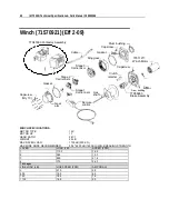
Page 62: ...tage 1 Carrier asm Sun gear Gasket Gear arm Capscrew Qty 10 Remote control Hex shaft Clutch retainer Drum bushing Drum support WINCH SPECIFICATIONS MOTOR TYPE 12V MOTOR HP 1 1 GEAR RATIO 261 1 WEIGHT 25 LB MAX RATED LOAD 1100 LB 500 KG MAX WIRE ROPE RECOMMENDED 3 16 4200 LB 1909 KG MIN BREAKING STRENGTH LAYER LOAD LB SPEED FPM 1 1100 16 9 2 965 19 3 3 859 21 6 4 775 24 0 1st Layer LINE LOAD LB LIN...

Page 63: ... LIST ITEM PART DESCRIPTION 1 77041800 CONTACTOR 2 COVER 3 SCREW 4 CABLE QUANTITY 2 5 DRUM BUSHING NYLATRON 6 CAPSCREW QUANTITY 2 7 DRUM SUPPORT 8 GASKET 9 RING GEAR 10 CARRIER ASSEMBLY STAGE 3 11 CARRIER ASSEMBLY STAGE 2 12 CARRIER ASSEMBLY STAGE 1 13 SUN GEAR 14 GEAR ARM 15 CAPSCREW QUANTITY 10 16 REMOTE CONTROL 17 HEX SHAFT ...

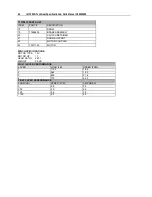
Page 64: ...Y 20 CLUTCH RETAINER 21 DRUM SUPPORT 22 MOTOR COUPLER 23 73511195 MOTOR WINCH SPECIFICATIONS MOTOR TYPE 12V MOTOR HP 1 1 GEAR RATIO 261 1 WEIGHT 25 LB MULTI LAYER PERFORMANCE LAYER LOAD LB SPEED FPM 1 1100 16 9 2 965 19 3 3 859 21 6 4 775 24 0 FIRST LAYER PERFORMANCE LOAD LB SPEED FPM AMP DRAW 0 6 5 38 500 5 9 65 750 5 6 78 1100 5 2 99 ...

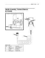
Page 65: ...Assembly Tethered Remote 51721683 1 2 3 4 5 7 6 7 6 7 HANDSET WIRING FROM BACK OF HANDSET WIRING CHART PIN COLOR FUNCTION A RED HOT TO SWITCHES B GREEN BLACK WINCH DOWN C GREEN WINCH UP D WHITE ROTATE CW E WHITE BLACK ROTATE CCW ...

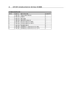
Page 66: ...ESCRIPTION QUANTITY 1 77041813 CABLE END CRANE 1 2 77041814 CABLE 1 3 77041815 HOUSING 1 4 77041816 REMOTE OVERLAY 1 5 77041817 TOGGLE SWITCH SPST 1 6 77041818 TOGGLE SWITCH DPDT 2 7 77041819 RUBBER BOOT 3 8 77041820 TERMINAL A FEM 250 FI 14 16 BL 2 9 77041821 TERMINAL B FEM 250 FI 10 12 YW 1 ...

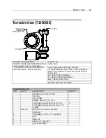
Page 67: ...WISE ROTATION OF MOTOR WEN VIEWED FROM MOTOR SHAFT END 40 1 REDUCTION IN PRIMARY 61 1 REDUCTION IN SECONDARY 2440 1 REDUCTION TOTAL SLEWING RING NOT INCLUDED 71056635 PARTS LIST ITEM PART DESCRIPTION QUANTITY 1 BEARING ROLL CUP CONE 2 2 OIL SEAL 2 3 CAP WORM 1 4 SCREW CBB 1 2 13 X 1 1 5 2 2 5 CAPSCREW HEX HEAD 1 4 20 NC X 3 4 12 6 CAPSCREW HEX HEAD 1 4 20 NC X 1 1 8 4 7 O RING 1 8 73511194 MOTOR 1...

Page 68: ... 1 18 SEAL OIL 1 19 OIL SEAL 1 20 GREASE FITTING 3 21 CAPSCREW 5 16 18 X 1 1 4 SH 4 22 ADAPTER 1 23 WORM GROUND 1 24 HOUSING 1 25 O RING 1 26 BEARING BALL OPEN 1 27 GASKET 010 BROWN AS REQ 27 GASKET 0075 CLEAR AS REQ 27 GASKET 005 BLUE AS REQ 27 GASKET 003 GREEN AS REQ 28 GASKET 020 YELLOW 1 29 CAP WORM 1 30 SHIM WORM 005 BLUE 2 31 SNAP RING EXT 1 32 BEARING DOUBLE BALL SPECIAL 1 33 SNAP RING INT ...

Page 69: ... REAR STABILIZERS 10 11 ON ALL FOUR SIDES OF CARRIER VEHICLE 9 ON CRANE POWER CABLE CONNECTION AT VEHICLE BATTERY 95721546 PARTS LIST ITEM PART DESCRIPTION QUANTITY 1 70396778 DECAL 2003i IDENTIFICATION 2 2 70397481 DECAL 2003i CAPACITY PLACARD 2 3 71394083 DECAL LOAD BLOCK RATING 2 0 TON 2 4 70397351 DECAL REMOTE PENDANT STORAGE 1 5 70397413 DECAL IMT DIAMOND 4 5 X 9 2 6 70397411 DECAL GREASE WEE...

Page 70: ...SCONNECT 1 10 70397389 DECAL DANGER ELEC HZD 4 11 70397390 DECAL DANGER CR LOADLINE 4 12 70397444 DECAL DANGER ELECTRO TELES 1 13 70392864 DECAL WARNING STAB STAND CLEAR 4 14 70392982 DECAL SERVICE REPAIR 1 15 70392213 DECAL CAUTION DON T WASH WAX 1 16 70395090 DECAL GREASE WORM DRIVE BEARINGS 1 17 70392524 DECAL ROTATE CRANE WHILE GREASING 1 18 70392399 DECAL LUBRICATE WORM 1 19 70396614 DECAL DA...

Page 71: ...pection Checklist NOTICE The user of this form is responsible for determining that these inspections satisfy all applicable regulatory requirements OWNER COMPANY TYPE OF INSPECTION circle one CONTACT PERSON DAILY MONTHLY QUARTERLY ANNUAL CRANE MAKE MODEL DATE INSPECTED CRANE SERIAL NUMBER HOURMETER READING if applicable UNIT I D NUMBER INSPECTED BY print LOCATION OF UNIT SIGNATURE OF INSPECTOR C H...

Page 72: ...his inspection must be recorded and retained for a minimum of 3 months QUARTERLY Q Every three to four months or 300 hours of normal operation whichever comes first includes all daily and monthly inspection items plus items designated with a Q This inspection must be documented maintained and retained for a minimum of 12 months by the employer that conducts the inspection ANNUAL A Each year or 120...

Page 73: ...es specified by the equipment manufacturer s recommendations both before each shift and after each move and setup D 17 Operator cab windows Check windows for cracks breaks or other deficiencies which would hamper the operator s view D 18 Rails rail stops rail clamps and supporting surfaces Check rails rail stops rail clamps and supporting surfaces when the equipment has rail traveling D 19 Safety ...

Page 74: ...bearing for proper torque of all mounting bolts Q 47 Hardware Base mounting bolts for proper torque Q 48 Structure All structural members for deformation cracks and corrosion 49 Base 50 Stabilizer beams and legs 51 Mast 52 Inner Boom 53 Outer Boom 54 Extension s 55 Jib boom 56 Jib extension s 57 Other Q 58 Hardware Pins bearing shafts gears rollers and locking devices for wear cracks corrosion and...

Page 75: ... extension cylinder s 95 Other Q 96 Winch Winch sheaves and drums for damage abnormal wear abrasions and other irregularities Q 97 Hyd Filters Hydraulic filters for replacement per maintenance schedule A 98 Daily All daily inspection items A 99 Monthly All monthly inspection items A 100 Quarterly All quarterly inspection items A 101 Hyd Sys Hydraulic fluid change per maintenance schedule A 102 Con...

Page 76: ... considered for corrective actions Corrective action for a particular recommendation depends on the facts in each situation c Corrective actions CA repairs adjustments parts replacement etc are to be performed by a qualified person in accordance with all manufacturer s recommendations specifications and requirements NOTE Deficiencies X listed must be followed by the corresponding corrective action...

Page 77: ...Chapter 8 General Reference 75 X R CA ITEM EXPLANATION DATE CORRECTED ...

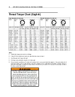
Page 78: ...10 1 1 4 7 1 25 1120 840 1815 1360 1 3 8 12 1 375 1675 1255 2710 2035 1 3 8 6 1 375 1470 1100 2380 1780 1 1 2 12 1 5 2195 1645 3560 2670 1 1 2 6 1 5 1950 1460 3160 2370 NOTES 1 Tightening torques provided are midrange 2 Consult bolt manufacturer s particular specifications when provided 3 Use flat washers of equal strength 4 All torque measurements are given in foot pounds 5 Torque values specifie...

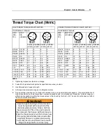
Page 79: ...12 1 375 232 174 375 281 1 3 8 6 1 375 203 152 329 246 1 1 2 12 1 5 304 228 492 369 1 1 2 6 1 5 270 210 438 328 NOTES 1 Tightening torques provided are midrange 2 Consult bolt manufacturer s particular specifications when provided 3 Use flat washers of equal strength 4 All torque measurements are given in kilogram meters 5 Torque values specified are for bolts with residual oils or no special lubr...

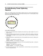
Page 80: ...rque value to apply to the size of capscrew used 2 Follow the tightening sequence shown in the diagram Note that the quantity of capscrews may differ from the diagram but the sequence must follow the criss cross pattern as shown in the diagram 3 Torque all capscrews to approximately 40 of the specified torque value by following the sequence EXAMPLE 40 x 265 FT LB 106 FT LB EXAMPLE METRIC 40 x 36 K...

Page 81: ...ble gear If one or more of the above conditions exists further inspection may be required Limits are measured in TILT which is dependent on the internal clearances of the bearing TILT is the most practical determination of a bearings internal clearance once mounted on a crane You can measure the tilt using the Turntable Bearing Tilt Test see Turntable Bearing Tilt Test on page 80 Periodic readings...

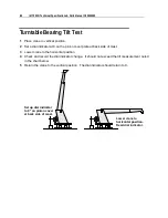
Page 82: ...e at back side of mast 3 Lower crane to the horizontal position 4 Check and record the dial indicator change It should not exceed the tilt measurement noted in the chart below 5 Return the crane to the vertical position The dial indicator should return to 0 Set up dial indicator to 0 on pinion cover at back side of mast Lower crane to horizontal position Read dial indicator ...

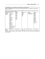
Page 83: ...rane Loader or Tirehand Model 1007 1014 1014A 1015 2015 2020 2109 2820 3000 3016 3020 3203i 3816 3820 4004i 421 425 4300 5005i 5016 5020 6006i 6016 6020 6022 5525 6025 6625 EZ Hauler I II EZ Hauler 3000 5500 5200 5200R 5217 5800 7020 7025 7200 7415 8025 9000 16000 I II III 32018 32027 32030 T30 T40 23516 14K160TH COMMANDER IV 1221R 1225R 8000L 9800 12916 13031 13034 14000 15000 18000 20017 8000L H...

Reviews: