background image

Electrical & Lighting 97 

Section - 5

4004i - Manual # 99904386 

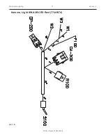
Harness, Light SW A2B CRD Reel (77441674) 

REV. B

Summary of Contents for 4004i

Page 1: ...l rights reserved No part of this publication may be reproduced stored in a retrieval system or transmitted in any form or by any means electronic mechanical photocopying recording or otherwise withou...

Page 2: ...f California to cause cancer and birth defects or other reproductive harm To minimize exposure avoid breathing exhaust do not idle the engine except as necessary service your vehicle or equipment in a...

Page 3: ...ylinder Extension 51725007 54 Cylinder Extension 51722111 56 Winch 71570922 58 Snatch Block 51724950 59 Power Unit 73511283 12V 73511305 24V 60 Power Unit 73511169 62 Hydraulic Installation 99904388 6...

Page 4: ...This page left intentionally blank iv 4004i Manual 99904386...

Page 5: ...Introduction 1 Section 1 4004i Manual 99904386 Introduction Section 1...

Page 6: ...nit This crane was designed and built to meet the standards of ANSI ASSE A10 31 1995 Safety Requirements Definitions and Specifications for Digger Derricks Contact the American National Standards Inst...

Page 7: ...Specifications 3 Section 2 4004i Manual 99904386 Specifications Section 2...

Page 8: ...acity 1 5 gallons 5 7 L Oil Type ISO VG32 Low Pour Anti Wear Hydraulic Oil CENTER OF GRAVITY Horizontal from Centerline of Rotation Booms Retracted 32 81 3 cm Horizontal from Centerline of Rotation Bo...

Page 9: ...battery Must meet chassis manufacturer s specifications Batteries must be fully charged prior to use Alternator 200 Amperes MINIMUM Engine Elevated RPM required if additional high amperage draw system...

Page 10: ...490 1585 3020 1370 1980 900 1450 660 1270 575 2680 1215 1080 490 1500 680 2330 1055 Maximum 1 part line capacity is 2000 lb 907 kg For greater loads use 2 part line NOTE LBS KG denote 2 part line 14 4...

Page 11: ...Specifications 7 Section 2 4004i Manual 99904386 Geometric Configuration 16 10 5 14 m 13 0 3 96 m 9 5 2 87 m 8 0 2 43 m 12 0 3 65 m 16 0 4 87 m 4 2 1 28 m 3 2 96 cm 2 3 67 4 cm 4004i 1 4 40 cm...

Page 12: ...ermittently all day using the duty cycles per the S2 and S3 curves or at full power for 4 5 minutes which MUST be followed by a complete cool down to ambient 180 AMPS 0 1 2 3 4 5 6 0 0 5 0 10 0 15 0 2...

Page 13: ...Specifications 9 Section 3 4004i Manual 99904386 Crane Reference Section 3...

Page 14: ...OWER BOOM PIN 7 SNATCH BLOCK NOTE All application points must be greased weekly under normal workloads and moderate weather condi tions Under severe operating conditions lubricate more frequently See...

Page 15: ...60178 CAP SCR 62 11X 4 00 HH 31 73511157 MOTOR HYD 101 1702 009 1 76039295 GASKET GEAR 1 77441534 SWITCH 225A CONTACTOR 12V OR 24V 1 73734304 VALVE BANK 12V 73540327 COIL VALVE BANK 12V 3 73540326 VAL...

Page 16: ...6 5 CRIT 1 72661543 PIN QUICK 316 10QP 2 60133938 WEAR PAD ROUND 0 25 X 1 00 X 0 50 X 0 50 2 72661711 CLEVIS PIN 0 5 X 3 00 1 99904327 CRANE WINCH ASSEMBLY 51721494 CORD REEL ASSEMBLY 5FT PACKARD CONN...

Page 17: ...HOLDER HIGH AMP2 BOLT WITH COVER 4 2 12 77441219 FUSE 225 AMP 4 2 13 89044276 CABLE 1 WELDING 1 4 35 FT 14 89392333 TUBE HEAT SHRINK AMP 1 4 0 50 FT 15 72060208 CAP SCREW 75 10X 2 50 HH GR8 Z 2 4 16 7...

Page 18: ...14 75 12 0 81 DIA 9 5 DIA 6 5 75 6 7 38 11 5 12 14 CRANE INSTALLATION CONTINUED NOTE The 3 4 10 x 2 5 grade 8 zinc coated capscrews are designed for a crane box thickness of 1 2 only A different crane...

Page 19: ...to length after determining the lengths required 5 Ground the crane by connecting the crane ground cable to bare metal inside the crane box 6 Connect the crane power cable from the male power cable c...

Page 20: ...ody A 1 3 7 1 4 9 POWER CABLE BRACKET GROUND CABLE GROUND TO BARE METAL INSIDE CRANE BOX MALE POWER CABLE CONNECTOR 89044276 13 ON OFF SWITCH TO FUSE CUT TO LENGTH WARNING Install the ground cable to...

Page 21: ...erminals item 10 77040529 Heat shrink connections NOTES 1 Use bulkhead pass through connectors when power or ground passes through a compartment wall 2 Reference drawing 99904884 for wiring diagram 1...

Page 22: ...ecifications 18 Crane Reference 4004i Manual 99904386 Electric Crane Battery Circuit 99904884 NOTE 1 Electric bulkhead pass thru connector Use whenever power or ground passes through a compartment wal...

Page 23: ...not factory installed on a body the crane is packed with the boom oriented as it is built on a test stand to facilitate handling Install the crane on the body with boom pointing backward Once the cra...

Page 24: ...tric Cranes are controlled by radio or tethered remote controls This telescopic crane includes a tethered remote control with a radio remote control option For complete details on operating your teles...

Page 25: ...Parts 21 Section 4 4004i Manual 99904386 Parts Section 4...

Page 26: ...r boom mast or crane base When ordering parts communicating warranty information or referring to the unit in correspondence always include the serial number and model numbers Address all inquiries to...

Page 27: ...N Each of the major weldments base mast inner boom outer boom extension boom and stabilizer weldments bear a stamped part number Any time a major weldment is replaced you must specify the complete par...

Page 28: ...Electrocution Hazard Never approach this vehicle or the load if it is near power lines Death or serious injury will result from touching or being near this vehicle if it becomes charged POWER SWITCH...

Page 29: ...This page left intentionally blank 25 4004i Manual 99904386...

Page 30: ...5 33 5 22 26 22 29 28 45 33 31 17 19 22 29 18 11 21 29 28 8 28 21 29 28 TORQUE TO 160 FT LBS APPLY RUST PREVENTATIVE SEE NOTE 1 APPLY RUST PREVENTATIVE TORQUE TO 160 FT LBS HYDRAULIC MOTOR VALVE BANK...

Page 31: ...1 1 20 70034382 CAP GREASE PRO20 GC RED 1 5 21 72060000 CAP SCR 25 20X 50 HH GR5 Z 1 3 22 72060002 CAP SCR 25 20X 75 HH GR5 Z 1 7 23 72060044 CAP SCR 38 16X 75 HH GR5 Z 1 1 24 72060046 CAP SCR 38 16X...

Page 32: ...063003 WASHER 38 FLAT 1 4 49 72062103 NUT 38 16 HEX NYLOCK 1 2 50 72060048 CAP SCR 38 16X 1 50 HH GR5 Z 1 2 51 71415014 KEEPER PIN 38 1 REV N CN885 NOTE 1 Apply black molub alloy 936 sf heavy gear gre...

Page 33: ...51721375 KIT HRDW BASE MAST 4004I REF 4 51721268 CYL 3 5 1 7 16 06S 30 44CC C 1 7 60140618 PIN TYPE NN 1 00 X 8 25 1 20 70034382 CAP GREASE PRO20 GC RED 1 5 24 72060046 CAP SCR 38 16X 1 00 HH GR5 Z 1...

Page 34: ...n 4 4004i Manual 99904386 Valve Bank 73734304 SAE 4 ORB PORT 2 438 6 284 SAE 4 ORB PORT 4 PLACES SAE 4 ORB PORT SAE 4 ORB PORT 2 PLACES 2 3 3 2 3 3 2 3 3 1 4 4 4 4 4 4 4 ROTATE HYDRAULIC SCHEMATIC MAI...

Page 35: ...3 73540327 VALVE COIL 12VDC FOR 73540326 4 7MM EXPANDER PLUG TESTING PROCEDURES SETUP CONNECT A PUMP CABLE OF 3 GPM AND 3000PSI TO P CONNECT T TO TANK CAP ALL OTHER PORTS TEST APPLY FLOW TO P AND VERI...

Page 36: ...arts 32 Section 4 4004i Manual 99904386 Cylinder Lower 51721268 SECTION B B B B 15 14 15 13 8 12 3 7 17 16 17 10 6 9 PRESS IN P N 60125699 2 19 21 11 2 8 3 7 17 16 4 17 10 6 9 11 12 15 5 14 15 13 19 2...

Page 37: ...3 12X 3 50X 19 70 1 1 12 7Q10P338 BACKUP RING 3 12 ID X 3 50 OD 1 1 13 7R14P017 ROD WIPER TYPE D 1 75 ROD 1 1 14 7R546017 U CUP SEAL LSU 1 50 ID X 2 00D 1 1 15 7T2NX420 WEAR RING ROD 1 75 ID X 0 50 W...

Page 38: ...7 13 20 9 20 9 18 22 23 23 10 11 16 24 24 19 29 28 5 CONNECT THE WIRE TERMINALS 77040051 TO COMMON AND NORMALLY OPEN ON ATB SWITCH 7 33 30 22 18 22 52 43 43 41 52 22 42 40 41 44 45 25 46 47 8 50 48 50...

Page 39: ...NUT 44 14 HEX NYLOCK 3 1 20 72062106 NUT 10 24 HEX NYLOCK 3 2 21 72062207 NUT 8 32 HEX NYLOCK 3 3 22 72063001 WASHER 25 FLAT 3 7 23 72063002 WASHER 31 FLAT 3 3 24 72063004 WASHER 44 FLAT 3 2 25 72063...

Page 40: ...4503 COVER ELEC CONTACTOR 1 48 52725097 WLDMT WINCH CONTACTOR BRKT 1 49 72601805 CAP SCR M12 1 75X 25 HHZ 3 2 50 72602011 SCR MACH 8 32X 62 BTNHD ZC 3 6 51 60140653 COVER VALVE BANK 3203I 1 52 7206000...

Page 41: ...1 FLAT 3 3 25 72063049 WASHER 25 LOCK 3 6 26 72063051 WASHER 38 LOCK 3 2 31 72601941 SCR MACH 25 20X 38 BTNHD ZC 3 1 37 60140618 PIN TYPE NN 1 00 X 8 25 1 38 71415014 KEEPER PIN 38 2 39 60140617 PIN T...

Page 42: ...9904327 2 ITEM NO PART NO DESCRIPTION KIT NO QTY 4 51724950 SNATCH BLOCK 3203I 4004I 1 6 70580197 WIRE ROPE ASM 25 7X19 GAC X 75 RRL 1 53 70735101 HOOK SWVL POS LOCK BBRG 2TON 2 REV X CN885 6 6 4 4 53...

Page 43: ...This page left intentionally blank 39 4004i Manual 99904386...

Page 44: ...Parts 40 Section 4 4004i Manual 99904386 Boom Assembly 99904326 8 9 8 18 16 7 2 20 9 4 20 17 10 22 17 22 11 10 5 3 21 21 22 22 23 13 26 25 BOOM ASSEMBLY 1 HYDRAULIC EXTENSION 1 MANUAL EXTENSION...

Page 45: ...2302 STOP SCREW 3 8 24 X 50 4 11 71734311 PIN QUICK RLSE 62D 4 5 CRIT 1 12 71734314 PIN QUICK RLSE 62D 5 75 CRIT 1 13 72060928 CAP SCR 50 13X 2 25 HH GR5 Z 1 1 14 72062104 NUT 25 20 HEX NYLOCK 1 2 15...

Page 46: ...Parts 42 Section 4 4004i Manual 99904386 BOOM ASSEMBLY 2 MANUAL EXTENSIONS...

Page 47: ...R PAD RND 0 30X 3 50X 1 00X 0 615 2 10 60132302 STOP SCREW 3 8 24 X 50 2 11 71734311 PIN QUICK RLSE 62D 4 5 CRIT 1 12 71734314 PIN QUICK RLSE 62D 5 75 CRIT 1 13 72060928 CAP SCR 50 13X 2 25 HH GR5 Z 1...

Page 48: ...Parts 44 Section 4 4004i Manual 99904386 BOOM ASSEMBLY 1 HYDRAULIC EXTENSION 20 9 20 8 8 9 6 7 16 18 2 3 BOOM ASSEMBLY 1 HYDRAULIC EXTENSION 25 23 13...

Page 49: ...AR PAD RND 0 25X 1 00X 50X 31 2 9 60030376 WEAR PAD RND 0 30X 3 50X 1 00X 0 615 2 10 60132302 STOP SCREW 3 8 24 X 50 4 11 71734311 PIN QUICK RLSE 62D 4 5 CRIT 1 12 71734314 PIN QUICK RLSE 62D 5 75 CRI...

Page 50: ...Parts 46 Section 4 4004i Manual 99904386 BOOM ASSEMBLY 1 MANUAL EXTENSION 3 10 17 8 9 8 12 10 17 6 9 20 20 BOOM ASSEMBLY 1 MANUAL EXTENSION 25 23 26...

Page 51: ...8 60030374 WEAR PAD RND 0 25X 1 00X 50X 31 2 9 60030376 WEAR PAD RND 0 30X 3 50X 1 00X 0 615 2 10 60132302 STOP SCREW 3 8 24 X 50 4 12 71734314 PIN QUICK RLSE 62D 5 75 CRIT 1 13 72060928 CAP SCR 50 13...

Page 52: ...Parts 48 Section 4 4004i Manual 99904386 BOOM ASSEMBLY 1 HYDRAULIC EXTENSION 1 MANUAL EXTENSION 14 15 24 15 15 24 15 14 10 17 17 10 11 BOOM ASSEMBLY 1 HYDRAULIC EXTENSION 1 MANUAL EXTENSION 25 23 26...

Page 53: ...132302 STOP SCREW 3 8 24 X 50 2 11 71734311 PIN QUICK RLSE 62D 4 5 CRIT 1 14 72062104 NUT 25 20 HEX NYLOCK 1 2 15 72063001 WASHER 25 FLAT 1 4 17 72063051 WASHER 38 LOCK 1 4 23 72661711 CLEVIS PIN 50 X...

Page 54: ...Parts 50 Section 4 4004i Manual 99904386 BOOM ASSEMBLY MANUAL EXTENSIONS 15 24 15 14 15 24 15 14 10 17 10 17 17 10 11 17 10 12 BOOM ASSEMBLY MANUAL EXTENSIONS 23 25 26 26...

Page 55: ...3 BOOM ASY 1 10 60132302 STOP SCREW 3 8 24 X 50 4 11 71734311 PIN QUICK RLSE 62D 4 5 CRIT 1 12 71734314 PIN QUICK RLSE 62D 5 75 CRIT 1 17 72063051 WASHER 38 LOCK 1 4 23 72661711 CLEVIS PIN 50 X 3 00 R...

Page 56: ...Parts 52 Section 4 4004i Manual 99904386 Snatch Block 51724950 1 9 2 1 3 5 3 6 7 9 8 8 10...

Page 57: ...HEAVE PLATE 3203I 2 2 60030482 SHEAVE 5 5 NYLATRON GSM 0 75 BORE 1 3 72661711 CLEVIS PIN 50 X 3 00 2 5 52704828 PIN TYPE T 75X 3 00 1 6 72053508 ZERK NPT 12 1 7 72066145 HAIR PIN 19 ZINC 1 8 60030243...

Page 58: ...Parts 54 Section 4 4004i Manual 99904386 Cylinder Extension 51725007 SECTION A A A A 8 4 15 11 12 10 6 7 13 9 13 5 3 14 11 4 15 12 10 6 13 7 9 13 5 8 3 2 14...

Page 59: ...1 1 13 76534503 U CUP LOADED 1 25X1 50X 250 B 1 2 14 7Q072018 O RING 75X 88X 06 70 1 1 15 7Q072129 O RING 1 56X 1 75X 09 70 1 1 REV A EFFECTIVE 2013 51725007 CYLINDER DATA CASE 5 cm 1 88 O D X 3 8 cm...

Page 60: ...SCR TORQUE CARTRIDGE TORQUE HEAD TORQUE PISTON TORQUE BRG SPAN TEST PSI OPER PSI DRY WEIGHT 1 77 SQ IN X 0 37 GAL 0 98 SQ IN X 0 20 GAL 1 88 OD X 1 50B X 58 25LG 1 00 OD X 61 38LG 0 75 X 2 750LG 48 0...

Page 61: ...RON 1 5 60132170 STINGER LOCK 75 16 X 1 75 LG 1 6 60132173 STOP TUBE 1 00 ROD X 4 00 LONG 1 7 60135106 PISTON 1 50 BORE X 75 STGR DUCT IRON 1 8 73054999 VALVE CBAL SUN01 CBBC LHN 1 9 76397127 WEAR RIN...

Page 62: ...511210 Contactor IMT P N 77041862 CAPSCREW QTY 10 GEAR HOUSING 76394906 GASKET PLUG CLUTCH GEAR INPUT RING GEAR CARRIER ASM RING GEAR GASKET BOLT QTY 3 SPACER QTY 3 76394906 32000212 BUSHING 32000388...

Page 63: ...82 SHEAVE 5 5 NYLATRON GSM 0 75 BORE 1 3 72661711 CLEVIS PIN 50 X 3 00 2 5 52704828 PIN TYPE T 75X 3 00 1 6 72053508 ZERK NPT 12 1 7 72066145 HAIR PIN 19 ZINC 1 8 60030243 SPACER POL 52X 1 50X 50 2 9...

Page 64: ...Parts 60 Section 4 4004i Manual 99904386 Power Unit 73511283 12V 73511305 24V 4 5 7 6 2 3 1...

Page 65: ...77043066 MOTOR 24VDC 2 73511306 PUMP 3 73540517 RELIEF VALVE ASSEMBLY 4 74399495 RESERVOIR 5 70734788 BREATHER CAP 6 73734791 TUBE SUCTION 7 70734792 STRAINER REV INITIAL RELEASE NOTES For parts not...

Page 66: ...tor 77043060 Fan Shroud Car t r i dge V a lv e Chec k V a lv e Adaptor Relief V a lv e 73540323 Retur n Line Pipe Relief Valv e Gear Pump 73511170 Suction Line Pipe Retur n Line Pipe Breather Cap 7339...

Page 67: ...LIC MOTOR PORT A PRESSURE EXTENSION CYLINDER RETRACT PORT EXTENSION CYLINDER EXTEND PORT LOWER CYLINDER RETRACT PORT LOWER CYLINDER EXTEND PORT EXTENSION CYLINDER OUT EXTENSION CYLINDER IN ROTATION CL...

Page 68: ...AR OF MAST WITHOUT PROPORTIONAL VALVE 14 11 11 12 15 15 EXTENSION CYLINDER WITH EXTENSION CYLINDER FRONT OF MAST 12 12 12 12 12 18 17 16 12 12 10 19 TO LOWER CYLINDER PORT R TO VALVE BANK PORT B2 TO V...

Page 69: ...DPTR M STR M JIC 10 4 5 2 16 51395219 HOSE FF 25 X 18 00 4 4 100R17 5 1 17 51395872 HOSE FF 25 X 21 00 4 4 100R17 5 1 18 72534547 ELBOW STREET STL 12 X 45 DEG 5 1 19 51395380 HOSE FF 25 X 22 00 4 6 10...

Page 70: ...AST WITH PROPORTIONAL VALVE SEE NOTE 14 29 11 11 28 12 27 11 15 15 EXTENSION CYLINDER WITH EXTENSION CYLINDER FRONT OF MAST 12 12 12 12 12 12 NOTE 1 CRANES WITHOUT EXTENSION CYLINDER USE PLUGS 7253252...

Page 71: ...M STR M JIC 10 4 5 2 16 51395219 HOSE FF 25 X 18 00 4 4 100R17 5 1 17 51395872 HOSE FF 25 X 21 00 4 4 100R17 5 1 18 72534547 ELBOW STREET STL 12 X 45 DEG 5 1 19 51395380 HOSE FF 25 X 22 00 4 6 100R17...

Page 72: ...YLINDER FRONT OF MAST 12 12 12 3 3 TO LOWER CYLINDER PORT E TO VALVE BANK PORT A2 10 12 12 NOTE 1 CRANES WITHOUT EXTENSION CYLINDER USE PLUGS 72532522 TO BLOCK HYDRAULIC PORTS B1 A1 ON THE VALVE BLOCK...

Page 73: ...ADPTR M STR M JIC 10 4 5 2 16 51395219 HOSE FF 25 X 18 00 4 4 100R17 5 1 17 51395872 HOSE FF 25 X 21 00 4 4 100R17 5 1 18 72534547 ELBOW STREET STL 12 X 45 DEG 5 1 19 51395380 HOSE FF 25 X 22 00 4 6 1...

Page 74: ...Parts 70 Section 4 4004i Manual 99904386 Tethered Control Installation 99904593 3203i 4004i CRANE TETHERED CONTROLS 10 7 5 10 8 14 4...

Page 75: ...TETHERED ELECTRIC CRANE REF 2 91725111 CONTROL KIT TETHERED ELECTRIC CRANE 3203 4004 X REF 4 70734746 HANDLE ASM TETHERED ELECTRIC CRANES X 1 5 60133633 COVER WINDOW X 1 7 72060002 CAP SCR 25 20X 75...

Page 76: ...Parts 72 Section 4 4004i Manual 99904386 Radio Control Installation Standard 99904594 3203i 4004i CRANE ON OFF RADIO CONTROLS 7 8 3 2 8 6 4...

Page 77: ...O ELECTRIC CRANE CRANE 1 1 4 70734348 TRANSMITTER RADIO ELECTRIC CRANE PROP 1 1 5 70734988 CABLE ASM 33FT 5 PIN RADIO ELIMINATION 1 1 7 72060008 CAP SCR 25 20X 2 00 HH GR5 Z 1 2 8 72062104 NUT 25 20 H...

Page 78: ...This page left intentionally blank 74 4004i Manual 99904386...

Page 79: ...Electrical Lighting 75 Section 5 4004i Manual 99904386 Electrical Lighting Section 5...

Page 80: ...92 14 6 8 9 7 16 10 14 MAST LH SIDE GROUND MAST REAR PLATE GROUND TO 300 AMP KEYED SWITCH IN CRANE BOX 5 4 SEE NOTE 1 11 12 ELECTRIC ROTATOR BRACKET TOP ELECTRIC ROTATOR BRACKET BOTTOM CRANE BOX TO CR...

Page 81: ...16RNG X 1 4RNG X 19 00LG 1 1 9 51721499 CABLE ASM 2GA 5 16RNG X 1 4RNG X 26 50LG 1 1 10 51721664 CABLE ASM 1GA 5 16RNGX 1 4RNGX 48 00LG 1 1 11 51721943 CABLE ASM 1GA 3 8RNGX SWVL FX 11 00LG 1 1 12 51...

Page 82: ...NO PART NO DESCRIPTION KIT NO QTY 1 51727279 ELECT KIT BOOM FLOOD LIGHTS 3203I 4004I 1 2 60145332 SLEEVE TYPE C 44X 75X 25 1 2 3 60145055 BRACKET LIGHT 3203I 4004I 1 1 4 72060074 CAP SCR 44 14X 5 00...

Page 83: ...ITEM NO PART NO DESCRIPTION KIT NO QTY 1 51727279 ELECT KIT BOOM FLOOD LIGHTS 3203I 4004I 1 2 77044574 CONN PKRD WEATHERPACK 2 CAV FEMALE TOWER 1 4 3 77044927 CABLE SEAL PKRD WP MP 14 GA GREY 1 2 4 77...

Page 84: ...tion 5 4004i Manual 99904386 99906234 2 ITEM NO PART NO DESCRIPTION QTY 1 51727279 ELECT KIT BOOM FLOOD LIGHTS 3203I 4004I 1 2 51727416 CORD REEL ASM 4 75 W PACKARD CONN 3 WIR 1 3 60132111 BRKT CORD R...

Page 85: ...6234 3 INSTALL TOGGLE SWITCH IN VALVE BANK COVER TO UP AS ON AND DOWN AS OFF NOTE TOGGLE SWITCH 77041345 IS PART OF HARNESS 77441674 INSTALL TOGGLE SWITCH IN VALVE BANK COVER TO UP AS ON AND DOWN AS O...

Page 86: ...6234 4 CP 400 CONNECTS TO NEW REEL DISCONNECTS FROM OLD REEL AND CONNECTS TO CJ 401 OR CONNECTS TO NEW LIMIT SWITCH CONNECTOR EXCESS HARNESS AND WIRES ARE ZIP TIED TO LIGHT BRACKET CJ 200 AND CJ 201 C...

Page 87: ...CREW ATTACH 1 4 WASHER CONNECTOR AND RE TIGHTEN TO 5 IN LB BOLT TO BACK OF MAST WITH 1 4 BOLT WASHERS AND NUT PROVIDED PLUG 3 WAY FEMALE CONNECTOR INTO NEW REEL WITH 3 PRONG MALE CONNECTOR PLUGS INTO...

Page 88: ...cal Lighting 84 Section 5 4004i Manual 99904386 275 225 Amp Contactor Replacement 99904578 2 5 3 7 9 6 4 8 SWITCH MOUNTED INSIDE MAST 275A CONTACTOR 2 5 3 7 10 8 4 6 SWITCH MOUNTED INSIDE MAST 225A CO...

Page 89: ...izontally by 4 9 vertically The mounting space for the 77441336 is 3 4 square 3 The 77441277 was mounted inside the mast as shown Use the replacement kit when mounting a replacement 77441336 inside th...

Page 90: ...This page left intentionally blank 86 4004i Manual 99904386...

Page 91: ...rness Radio 77441270 REV L CN773 CP 1201 CP 1200 A B A B 1 2 1 2 1 2 1 2 1 2 1 2 BOOM UP BOOM DOWN EXTEND OUT EXTEND IN ROTATE CW ROTATE CCW PROPORTIONAL 1 2 W1 W2 W3 HYDRAULIC PUMP POWER GROUND FUSED...

Page 92: ...Electrical Lighting 88 Section 5 4004i Manual 99904386 77441270 1 2 1 2 1 B A 2 2 1 1 A B 2 2 1 1 2 1 15A...

Page 93: ...Electrical Lighting 89 Section 5 4004i Manual 99904386 Harness Tethered 77441269 REV H...

Page 94: ...Electrical Lighting 90 Section 5 4004i Manual 99904386 77441269 1...

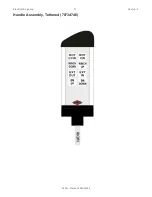
Page 95: ...Electrical Lighting 91 Section 5 4004i Manual 99904386 Handle Assembly Tethered 70734746...

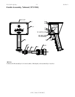
Page 96: ...ered 51721502 NOTES Tethered handle assembly is non serviceable If damaged a new assembly is required 2 13 7 21 30 8 20 3 26 23 BLACK S HYD PUMP TO SWITCH 19 SOLDER WIRE TO TERMINAL 4 10 25 24 28 29 1...

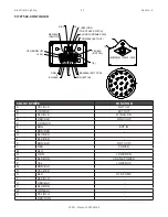
Page 97: ...ROT CCW 17 BRN EXT IN RE D RED BLK WIN UP 15 16 YEL BOOM UP SOLID STRIPE FUNCTION A YEL BLK ROT CW B ORN BLK EXT OUT C BLU BLK WINCH DN D RED BLK WINCH UP E ORN RED F BRN EXT IN G BRN RED H BLU RED J...

Page 98: ...3 4 X 1 2 1 14 72061009 SHT MTL SCR 6X3 4 PH 8 15 77040051 TERM SPRSPD 8 16 14GA 16 17 77040372 TOGGLE SWITCH SPDT 4 18 77040373 TOGGLE SWITCH SPST 1 20 77044579 CONNECTOR 1 21 89044100 CABLE 18GA 24W...

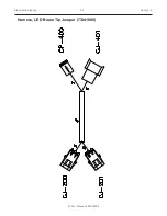
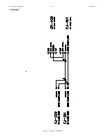
Page 99: ...Electrical Lighting 95 Section 5 4004i Manual 99904386 Harness LED Boom Tip Jumper 77441689...

Page 100: ...Electrical Lighting 96 Section 5 4004i Manual 99904386 77441689 1...

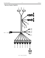
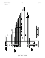
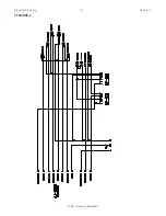
Page 101: ...Electrical Lighting 97 Section 5 4004i Manual 99904386 Harness Light SW A2B CRD Reel 77441674 REV B...

Page 102: ...Electrical Lighting 98 Section 5 4004i Manual 99904386 77441674 1 NOTE Seal contact 87A of R100 All wire White GXL Include washer and nut for S100 switch...

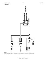
Page 103: ...Electrical Lighting 99 Section 5 4004i Manual 99904386 Harness Limit Switch Jumper 77441678...

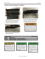
Page 104: ...a Lock Out Tag Out procedure follow OSHA 1910 147 Lock Out Tag Out SAFETY NOTICE Use appropriate Personal Protective Equipment PPE as required by your company Read and understand the following instruc...

Page 105: ...This page left intentionally blank 101 4004i Manual 99904386...

Page 106: ...General Information 102 Section 6 4004i Manual 99904386 General Information Section 6...

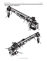
Page 107: ...General Information 103 Section 6 4004i Manual 99904386 Decal Installation 99904410 28 12 26 27 29 25 9 6 7 10 32 11 33 34 35 30 26 25 33 33 34 34 22 12 27 28...

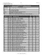
Page 108: ...RM DR BRNGS 1 1 1 11 70395324 DECAL ASME ANSI B30 5 TELESCOP 1 1 1 12 70395670 DECAL CAUTION DOWN HAUL WT 1 2 2 13 71391522 DECAL ANGLE INDICATOR RH 1 1 0 14 71391523 DECAL ANGLE INDICATOR LH 1 1 0 15...

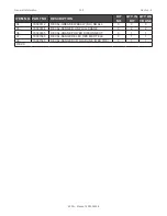
Page 109: ...TION KIT NO QTY IN KIT QTY ON CRANE 34 70397412 DECAL GREASE WEEKLY RH SMALL 3 3 3 35 70397404 DECAL DANGER UNPLUG CRANE 3 2 2 36 70397405 DECAL CRANE POWER DISCONNECT 3 1 1 37 70397389 DECAL DANGER E...

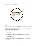
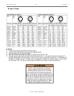
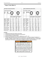
Page 110: ...ING PROCEDURE 1 Refer to the Torque Data Chart to determine the proper torque value to apply to the size of cap screw used 2 Follow the tightening sequence shown in the diagram 3 Torque all cap screws...

Page 111: ...9 14 27 20 5 16 18 0 3125 17 13 25 18 3 8 24 0 375 35 26 49 35 3 8 16 0 375 31 23 44 33 7 16 20 0 4375 55 41 78 58 7 16 14 0 4375 49 37 70 52 1 2 20 0 5 90 64 120 90 1 2 13 0 5 75 57 105 80 9 16 18 0...

Page 112: ...PLATED KG M PLAIN KG M PLATED KG M 5 16 24 0 3125 3 2 4 3 5 16 18 0 3125 2 2 3 2 3 8 24 0 375 5 4 7 5 3 8 16 0 375 4 3 6 5 7 16 20 0 4375 8 6 11 8 7 16 14 0 4375 7 5 10 7 1 2 20 0 5 12 9 17 12 1 2 13...

Page 113: ...scontinue manufacturing at any time without notice or obligation IMT and IMT LOGO are registered trademarks of Iowa Mold Tooling Co Inc Garner IA USA 2020 Iowa Mold Tooling Co Inc All Right Reserved I...

Reviews: