background image


Operation 35 


MINIMUM PRESSURE VALVE 

The minimum pressure valve is located at the outlet of the coalescer head and serves to 
maintain a minimum discharge pressure of 65 PSIG in operation, which is required to assure 
adequate compressor lubrication pressure. 

OIL FILTER 

The compressor oil filter is the full-flow replaceable element type. 

COMPRESSOR COOLING SYSTEM 

The compressor cooling system consists of a remote mounted oil/air cooler with an electric fan.  
The fan is activated through a temperature switch (180°) and latching relay, so it will not turn off 
until the compressor is disengaged and the system pressure is fully relieved, or when the engine 
is turned off.  The thermal valve will divert oil to the oil cooler at 160°F. 

ELECTRICAL AND SAFETY CIRCUIT SYSTEM 

The unit is supplied with an hourmeter, wire harness and a high temperature shutdown switch.  
Compressor shutdown occurs in the event of high compressor temperature (> 250°). 

AUTOMATIC BLOW DOWN VALVE 

There is one blow down valve in the compressor system.  It is located inside the compressor. 
The valve will automatically bleed the sump to atmospheric pressure when the compressor is 
disengaged.  The blow down time interval is typically less than 90 seconds. 

CONTROL SYSTEM 

The prime component of the compressor control system is the compressor inlet valve.  The 
control system is designed to match air supply to air demand and to prevent excessive 
discharge pressure when compressor is at idle.  Control of air delivery is accomplished by the 
inlet valve regulation and modulation as directed by the discharge pressure regulator. 

PRESSURE REGULATOR VALVE 

This valve, located inside the compressor, is used to set the desired discharge pressure within 
the operating pressure range.  Turning the regulator screw clockwise increases the working 
pressure; a counterclockwise movement of the screw reduces the working pressure.  This 
system has a maximum operating pressure of 150 psi. 


Summary of Contents for CAS3560

Page 1: ...AX 641 923 2424 Website http www imt com Copyright 2009 Iowa Mold Tooling Co Inc All rights reserved No part of this publication may be reproduced stored in a retrieval system or transmitted in any fo...

Page 2: ......

Page 3: ...on 77441157 Effective 3 15 05 24 Electrical Installation Non IMT Application 77441084 Through 3 15 2005 24 Cooler Installation 99903573 25 Compressor Space Requirements 27 Decal Installation 99903551...

Page 4: ...y Complete Parts List 99903574 56 99903574 1 Drawing 60 99903574 2 Drawing 62 99903574 3 Drawing 64 99903574 4 Drawing 66 99903574 5 Drawing 68 Discharge Valve 70733872 70 Compressor Air End 71 Air In...

Page 5: ...532 ECN 9835 99903532 installation updates hose changes to 99903573 74 added 99903712 standard mounting locations 20050907 99903712 99903573 99903532 ECN 9907 Added note regarding 10 minimum space bet...

Page 6: ......

Page 7: ...legible The equipment owner and or designated employee is responsible for informing all operators maintenance personnel and others involved in equipment operation about the safe operation and mainten...

Page 8: ...his manual three means are used to draw the attention of personnel They are NOTEs CAUTIONs and WARNINGs and are defined as follows NOTE A NOTE is used to either convey additional information or to pro...

Page 9: ...ous in using this machine in flammable gas risk areas Use in these areas may require additional safety equipment such as gas detectors exhaust spark arrestors and shut off valves depending on local re...

Page 10: ...pressors for breathing air Do not disconnect or bypass safety circuit system Do not install safety devices other than authorized IMT replacement devices Close all openings and replace all covers and g...

Page 11: ...als must be affixed to the vehicle after it has been painted trimmed and undercoated etc and prior to being put into service The decal placement should ensure decals are clearly visible to the user an...

Page 12: ...10 IMT CAS3560 Air Compressor Manual Part No 99903566 Warning Caution Decals WARNING Do not operate with cover removed CAUTION Minimum 8 20 cm clearance on each end of compressor 70397804...

Page 13: ...PARKED ON LEVEL GROUND 2 FLUID LEVEL MUST FILL 1 2 to 3 4 OF THE SIGHTGLASS 3 DO NOT FILL ABOVE THE TOP OF THE SIGHTGLASS FILL OIL TO THIS LEVEL IN SIGHTGLASS OIL FILL HIGH TEMP RESET 8000 RPM MAX AI...

Page 14: ...capacity control system a lubricating oil system and a discharge system in addition to basic instrumentation The instrumentation includes a temperature gauge an hourmeter a hi temp warning indicator...

Page 15: ...ormance Charts on page 14 Lubrication Oil pump Oil pump Oil Capacity 6 qts 5 7 L Maximum Compressor Oil Temperature 250oF 121oC Maximum Hydraulic Oil Temperature 180oF 82oC Weight 365 lb wet 166 Kg we...

Page 16: ...raulic Oil Input 0 10 20 30 40 50 60 70 80 90 100 7 8 9 10 11 12 13 14 15 16 17 18 19 Oil Flow GPM Compressor Air Output vs Compressor Input Speed 0 10 20 30 40 50 60 70 80 90 100 3000 3500 4000 4500...

Page 17: ...0 20 30 40 50 60 70 80 90 100 5 0 7 0 9 0 11 0 13 0 15 0 17 0 19 0 21 0 23 0 25 0 Compressor Input HP Compressor Air Output vs Hydraulic Oil Pressure 0 10 20 30 40 50 60 70 80 90 100 1500 1600 1700 18...

Page 18: ...75 Input Power HP 8 9 11 8 14 7 17 6 20 5 Compressor Speed RPM 3956 4990 6020 7051 8082 Hydraulic Motor Speed RPM 2726 3438 4148 4858 5568 Hydraulic Motor Flow GPM 8 67 10 88 13 1 15 31 17 5 Hydrauli...

Page 19: ...24 Input Power Kw 6 6 8 8 10 9 13 1 15 3 Compressor Speed RPM 3956 4990 6020 7051 8082 Hydraulic Motor Speed RPM 2726 3438 4148 4858 5568 Hydraulic Motor Flow LPM 32 8 41 2 49 6 57 9 66 2 Hydraulic Mo...

Page 20: ...LB Pressure Switch 5 LB Pressure Switch Relay Module Oil Fill Tube Oil Filter Pressure Relief Valve Hydraulic Solenoid Hi Temp Shutdown Switch Temp Sender not shown visible from side or top Fan Fan T...

Page 21: ...ydraulic Connection Pressure In Hydraulic Connection Return to Tank Temperature Gauge Lighted Pushbutton Switch Oil Level Sightglass Visible through cut out Air Filter Indicator Connection for Oil Dra...

Page 22: ......

Page 23: ...mes with an IMT service truck without a crane the compressor will be wired through the truck and will be controlled with a switch If the compressor is sold individually it is up to the customer or his...

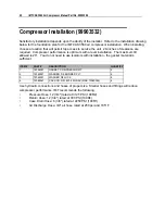
Page 24: ...llation The maximum tilt allowed is 20 You do not need to use isolators with installation the gasket material is sufficient ITEM PART DESCRIPTION QUANTITY 1 76396381 GASKET COMPRESSOR MT 2 2 72062821...

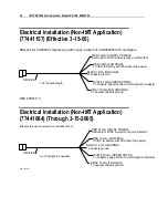
Page 25: ...INATOR HARNESS BLACK TO CHASSIS GROUND RED TO BATTERY POWER 12 VDC WITH 25A FUSE FRONT OF SIDEPACK 5 8 11 THREADS FOR LIFT EYE NOTE Maintain at least 8 of clearance on each end of the compressor When...

Page 26: ...NTRL To chassis speed control circuit signal to chassis GRAY 10GA FAN GROUND To nearest chassis ground 192 overall length SPLICES REV 20081113 Electrical Installation Non IMT Application 77441084 Thro...

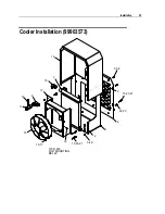
Page 27: ...Installation 25 Cooler Installation 99903573 6 22 23 19 20 21 2 3 5 8 18 7 10 13 9 12 11 15 16 17 77041676 FOR MOUNTING RELAY 14 19 20 21 3 4 5 2...

Page 28: ...ED B RED TO BATTERY 12VDC W 30A FUSE RED TO SWITCHED 12VDC GREEN TO PTO GROUND 77041676 RELAY 77641094 HARNESS 99903573 PARTS ITEM PART DESCRIPTION QUANTITY 1 52718363 MOUNT COOLER HYD 1 2 72062301 NU...

Page 29: ...5 16 18X1 HHGR5Z 4 23 72062109 NUT 5 16 18 HEX NYLOC 4 24 77441094 HARNESS AUX HYD COOLER 1 25 72060047 CAP SCR 3 8 16X1 25 HHGR5Z 4 REV E 20060523 NOTE When the compressor is installed with a hydrau...

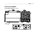
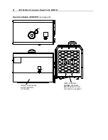
Page 30: ...All decals for the CAS3560 Compressor come on a single sheet of decals part number 95718232 See the decal sheet illustration for decal item numbers These items numbers are referred to in the placemen...

Page 31: ...903551 Decal Installation 99903551 on page 28 8 6 10 5 12 15 17 14 7 1 70396451 1 PER SIDE CAUTION Minimum 8 20 cm clearance on each end of compressor 70397804 CAUTION Minimum 8 20 cm clearance on eac...

Page 32: ...3560 Air Compressor Manual Part No 99903566 Decal Installation 99903551 on page 28 1 2 4 13 11 70396451 COMPRESSED AIR SYSTEM DECAL 1 PER SIDE 70029119 SERIAL NUMBER PLACARD MOUNTED WITH TWO POP RIVET...

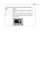
Page 33: ...LS NOT SHOWN ON PLACEMENT DRAWINGS ITEM LOCATION 2 Place 1 on 52718087 lift station near 70146433 relay module 3 Place in cab on the dash board on the passenger side 9 Place on 70146433 relay module o...

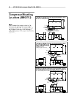
Page 34: ...the compressor aftercooler combination CAS3560 CAS2545 INSTALLATION ON SERIES 2 DOM WITH HEADACHE RACK STANDARD HEIGHT SIDEPACK ON COMPRESSOR SIDE AND TELESCOPIC ROOF 4 38 12 25 16 5 6 12 18 MIN 0 44...

Page 35: ...rst stage of oil separation from compressed air Also serves as reservoir area for compressor lubricant PSI Refers to the operating pressure the system is set up at expressed as pounds per square inch...

Page 36: ...the compressed air and seals the running clearances LUBRICATION SYSTEM Oil from the compressor oil sump at compressor discharge pressure is directed through the oil filter cooling system and to the si...

Page 37: ...sor shutdown occurs in the event of high compressor temperature 250 AUTOMATIC BLOW DOWN VALVE There is one blow down valve in the compressor system It is located inside the compressor The valve will a...

Page 38: ...nt temperature Condensation is directed to the air tank where it is collected CONTROL SYSTEM OPERATION The following discussion explains the operation of the control system from a condition of no load...

Page 39: ...ter may cause reduced air output The indicator will be in the red zone when the filter needs attention c Avoid operating the compressor package when the side to side or front to rear tilt is greater t...

Page 40: ...n the compressor oil temperature reaches 180 F the fan indicator light will turn on indicating that the fan is running Once the fan starts to run it will latch on and continue to run until the compres...

Page 41: ...ocation and environment Performing this maintenance will improve the performance of the system during sub zero temperature operation Use only IMT approved rotary screw compressor oils and filters 2 ST...

Page 42: ...y the compressor air end will exceed the maximum operating temperature If the system shuts down due to high temperature during sub zero temperature operation the oil will need to be warmed before rest...

Page 43: ...AINTENANCE CHART lists serviceable items on this compressor package The items are listed according to their frequency of maintenance followed by those items which need only As Required maintenance The...

Page 44: ...ves Check all electrical connections Air end oil change see Note 2 Inspect drive system for wear tension Air cleaner change Coalescer element change Service intervals are listed as hours months whiche...

Page 45: ...used with an eyehook or lifting hook to lift the compressor Lift hooks or eyehooks with a rating of at least 600 pounds must be provided by the customer COMPRESSOR OIL SUMP FILL LEVEL AND DRAIN CHECK...

Page 46: ...on in the air or oil system without first shutting off compressor and manually relieving pressure from the sump and air storage tank Failure to comply with this warning may cause damage to property an...

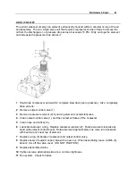
Page 47: ...l valve 1 3 Remove coalescer element 2 by turning element counterclockwise 4 Clean output control valve 1 and the contact surfaces of the coalescer 5 Clean hose end orifices 3 6 Lubricate coalescer o...

Page 48: ...ing a little oil to the seal and then screw the filter on by hand turning it clockwise until hand tight plus one third turn Do not use tools to tighten the filter 4 Check for leaks in operation 5 Re c...

Page 49: ...p of pulleys Push on top of belt to a deflection of 0 155 Measure force using belt tensioning gauge 79733864 5 With tool still in place tighten motor mount bolts Release tool 6 Re check belt deflectio...

Page 50: ...g a suitable heavy duty lubricant must rest with the individual supplier if they choose not to use the recommended IMT rotary screw lubricant The lubricant supplier s recommendation must therefore be...

Page 51: ...draulic solenoid relay Power Main power to solenoid Normal Operation When the compressor is turned on the Power and Enable relays will light indicating normal operation When the oil temperature reache...

Page 52: ...nd that there is no grinding present 2 Flush oil cooler a Remove both tubes from oil cooler b Verify that the plastic shroud and fan blades are intact Put power direct to red lead ground black lead at...

Page 53: ...through the valve block but not through the hydraulic motor High Temp Reset light should be active until depressed If compressor does not stop running DO NOT PROCEED Contact IMT Technical Support If...

Page 54: ...Air flow Insure that cooler has no airflow obstructions Check air cooler core Clean as needed High ambient air temperature Contact IMT Technical Support Leaks Check for air leaking from tank or blow d...

Page 55: ...ompressor shaft seal Replace seal Water in air system Defective moisture separator drain trap Inspect and clean if required Replace separator trap if required Air cooler core dirty Inspect and clean A...

Page 56: ...eck for 12 volts across 20 lb pressure switch N O If switch is not closing replace With the compressor off check for 12 volts across 5 lb pressure switch N C If switch does not close replace switch Sp...

Page 57: ...AULIC PUMP INFORMATION Compressor Model Serial Number Pump Make Model Reservoir Capacity Engine RPM Recommended Spare Parts List Part Description Qty 79733864 Belt tensioning gauge 1 92718151 Belt ten...

Page 58: ...N 1 16 72534358 ADPTR MPT FPT STL 12 12 1 17 70048222 INDICATOR AIR FILTER 1 18 72531534 NIPPLE BARB BRS 12MPT 25 220CF 2 19 89392146 HOSE GP 25X250 WP GRAY 801 4 3 20 72066452 CLAMP HOSE 25 62 SAE 4...

Page 59: ...8224 SENDER TEMPERATURE 1 59 77041662 SWITCH TEMP 1 2 250R NC 1 60 72533625 ADPTR M BSPP M JIC 16 12 1 61 72533656 ADPTR M BSPP M JIC 8 12 2 62 REF BASE 1 63 72661369 POP RIVET WAS 72534357 1 64 REF I...

Page 60: ...4 LOCK ZINC 4 108 72062206 NUT 4 40 HEX ZINC 4 109 60125303 COVER 1 110 72063228 WASHER NYLON PART OF 140 12 111 72063001 WASHER 25 FLAT PART OF 140 12 112 72601652 SCR MACH 25 20X 75TRHTORXSS PART OF...

Page 61: ...9 99093574 PARTS LIST ITEM PART DESCRIPTION QUANTITY 144 72534369 ELBOW 2BSPP 4COMP 2 145 72534370 TUBING CONTROL LINE PLASTIC 1 146 72063117 WASHER 7 16 FLAT 4 147 72063002 WASHER 5 16 FLAT 2 REV F 2...

Page 62: ...3566 99903574 1 Drawing Compressor Assembly Parts List 99903574 see Compressor Assembly Complete Parts List 99903574 on page 55 97 10 13 12 18 20 19 99 16 1 116 103 102 100 117 101 105 106 107 108 104...

Page 63: ...WASHER 38 LOCK 3 97 72053767 ELBOW M STR 90 M JIC 12 12 3 99 60125143 VALVE BLOCK 1 100 72532366 ADPTR M STR M JIC 12 12 3 101 73540127 VALVE SOLENOID 1 102 73540139 VALVE RELIEF 1 103 72532140 PLUG S...

Page 64: ...r Assembly Parts List 99903574 see Compressor Assembly Complete Parts List 99903574 on page 55 51 70 70 74 75 51 77 78 71 72 73 53 54 55 55 41 42 41 42 63 62 64 65 68 69 2 50 43 56 56 67 58 66 61 52 7...

Page 65: ...IC 16 12 1 61 72533656 ADPTR M BSPP M JIC 8 12 2 62 REF BASE 1 63 72661369 POP RIVET WAS 72534357 1 64 REF INTAKE 1 65 REF COVER 1 66 72062163 NUT METRIC 8MM X 1 25 1 67 76396154 INSERT RUBBER INLET 2...

Page 66: ...pressor Manual Part No 99903566 99903574 3 Drawing Compressor Assembly Parts List 99903574 see Compressor Assembly Complete Parts List 99903574 on page 55 59 78 53 54 3 81 79 4 57 126 43 85 84 86 54 8...

Page 67: ...4 72062109 NUT 31 18 HEX NYLOCK PART OF 141 7 57 72534355 ADPTR M BSPP FPT 4 4 1 59 77041662 SWITCH TEMP 1 2 250R NC 1 78 60125297 BRACKET LIFT 1 79 60125150 BRACKET AIR CLEANER 1 80 72060026 CAP SCR...

Page 68: ...8 39 31 31 34 31 35 28 117 46 127 96 12 44 97 116 12 45 12 45 29 SEAL PERIMETER WITH 119 AGAINST COOLER 44 AS REQ D FOR SHIMS 12 44 115 47 48 49 88 89 146 32 33 147 99903574 PARTS LIST ITEM PART DESCR...

Page 69: ...R 25 20X 75 HH GR5 Z PART OF 143 4 48 72063000 WASHER 19 W FLAT ANSI B27 2Z PART OF 143 4 49 72062104 NUT 25 20 HEX NYLOCK PART OF 143 4 87 73050184 MOTOR HYD 0 73 PISTON BENT AXIS 1 88 72060094 CAP S...

Page 70: ...LUMINUM GRILL 110 111 112 OIL FILTER 73396426 99903574 5 PARTS LIST ITEM PART DESCRIPTION QUANTITY 6 71410008 TUBE ASM AIR OUTPUT HOT 1 7 71410007 TUBE ASM AIR DISCHARGE 1 8 71410009 TUBE ASM OIL RETU...

Page 71: ...WAY METRIPAK TEMP SENDER RING TERMINAL HI TEMP SWITCH 2 WAY WEATHERPAK ELECTRICAL CONNECTIONS TO HARNESS 104 20 LB SWITCH 2 WAY WEATHERPAK 5 LB SWITCH 2 WAY METRIPAK RELAY MODULE 6 WEATHERPAK CONNECTO...

Page 72: ...Manual Part No 99903566 Discharge Valve 70733872 70733872 PARTS ITEM PART DESCRIPTION QUANTITY 94744119 SEAL KIT ASM 1 94744120 REPAIR KIT ASM 1 1 SLIDE RING 1 2 PISTON GASKET 1 3 PLATE GASKET 1 4 O...

Page 73: ...Parts 71 Compressor Air End COMPRESSOR AIR END PARTS ITEM PART DESCRIPTION QUANTITY 1 94744117 SHAFT SEAL ASM 1...

Page 74: ...6 Air Inlet Valve 70733873 70733873 PARTS LIST ITEM PART DESCRIPTION QUANTITY 94744121 SEAL KIT ASM INCL 1 5 1 94744122 REPAIR KIT ASM INCL 1 5 9 13 16 1 1 GASKET 1 2 O RING 1 3 GASKET 1 4 O RING 1 5...

Page 75: ...ematic 12V IGN PWR 10A ENABLE RELAY FAN RELAY 15A 12VDC FAN PWR FEED 30A 180 POWER RELAY 250 20 LB 5 LB TO SPEED CONTROL HYD SOL RELAY HI TEMP RELAY RELAY MODULE 70146433 M SOL VALVE HOUR METER TEMP S...

Page 76: ...74 IMT CAS3560 Air Compressor Manual Part No 99903566 Hydraulic Schematic HYD BLOCK HYD IN HYD OUT CASE DRAIN P T COMPRESSOR PACKAGE...

Page 77: ...auge Oil Filter Air Cooler Inlet Negative Control Valve Reservoir Recommended Ambient Air Air Filter Fan Switch N O 180 F Thermal Switch Speed Control Disable 5 psi N C Pressure Switch Speed Control E...

Reviews: