SECTION 2:
SPECIFICATIONS
SECTION 2: SPECIFICATIONS
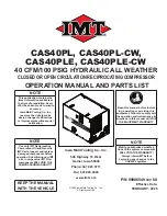
CAS40PL, CAS40PL-CW, CAS40PLE, CAS40PLE-CW
2.1 GENERAL
INTRODUCTION
The tables and
fi
gures in this section list the
speci
fi
cations (including operational, output and
dimensional) of the overall machine. Contact the
IMT
®
Service Department if additional speci
fi
-
cations are needed that cannot be found in this
manual.
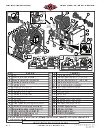
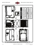
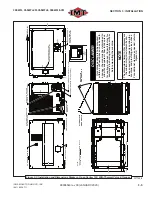
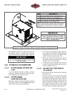
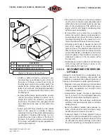
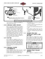
Refer to
Figure 2-1
for general machine compo-
nent locations. For additional information, includ-
ing measurement speci
fi
cations, refer to
Figure
3-1
(machine and identi
fi
cation and dimensions)
in
Section 3, Installation
.
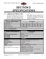
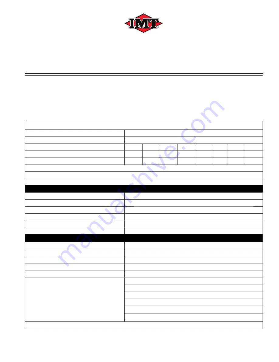
TABLE 2A: SPECIFICATIONS
GENERAL SYSTEM INFORMATION
SPECIFICATION
CFM Rating @ 100 psi:
30
I
40
II
Air Pressure (psi):
100
125
150
175
100
125
150
175
Hydraulic
fl
ow (gpm):
8.25
8.25
8.25
9.0
10
10
10
10
Hydraulic pressure (psig):
2300
2450
2575
2600
2300
2470
2550
2600
NOTE:
Compressor adjustment should be set in accordance with rated RPMs.
I
30 CFM = 690 COMPRESSOR RPM
II
40 CFM = 1100 COMPRESSOR RPM
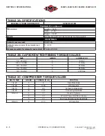
COMPRESSOR
GENERAL SYSTEM INFORMATION
SPECIFICATION
Type:
Two-stage, two cylinder, reciprocating
Compressor oil reservoir capacity:
3 quarts
Air inlet system:
Dry-type, single stage
Drive coupling:
Direct drive, coupled
Hydraulic motor:
Gear type
PACKAGE
Main frame:
Formed powder-coated steel with a bolt-down provision
Electrical supply:
12V Standard; 24V Optional
Electrical connections:
Weatherpack
Enclosure:
Aluminum, powder-coated
Cooler:
Hydraulic oil cooler/radiator core — electric fan
Package connections:
(Refer to
Figures 3-1
and
3-2
in Section 3)
Discharge air — 3/4” JIC male
Hydraulic supply — 3/4” 37° JIC male
Hydraulic return — 1” 37° JIC male
Load sense line (closed center only) — 1/4” 37° JIC male
+12VDC or +24VDC (PTO activated)
Motor case drain 3/8" 37° JIC male
Continued on next page
99906549 rev 00 (JANUARY-2020)
2 - 2
IOWA MOLD TOOLING CO., INC.
(641) 923-3711
Summary of Contents for CAS40PL
Page 2: ...BLANK PAGE...
Page 81: ...BLANK PAGE...

