3 - 2
99906549 rev 00 (JANUARY-2020)
SECTION 3: INSTALLATION
IOWA MOLD TOOLING CO., INC.
(641) 923-3711
CAS40PL, CAS40PL-CW, CAS40PLE, CAS40PLE-CW
3.3 DETERMINING THE CAS40PL
UNIT MOUNTING LOCATION
When determining the location to mount the
CAS40PL unit, the following criteria must be tak-
en into consideration:
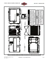
• The mounting surface must be level and able to
accommodate the four (4) mounting bolts and
isolators of the base frame. Refer to
Figure
3-1
or
Figure 3-2
for layout of mounting hole
slots’ locations.
IMPORTANT
Mounting surface must be able to bear the
weight of the machine (255-260 lbs, wet).
• Mount the machine with a minimum of four (4)
mounting locations.
• The location must allow for the machine dimen-
sions, and additional space requirements for
minimum cooling, maintenance and access.
Refer to
Figure 3-3
to determine the additional
minimum space requirement measurements.
• The external gauges/display must be easily
visible to the operator.
It is recommended, for most installations, to
mount the compressor on the driver’s side of the
vehicle. The unit should be situated in such a
manner that the fan (rear) and hydraulic cooler
(front) are not obstructed. Do not place the com-
pressor in any location where it can ingest ex-
haust fumes, dust or debris.
NOTE
When considering external system layout hoses
refer to Section
7.22, Hose Guide
for proper
routing and mounting practices.
3.4 HYDRAULIC
SYSTEM
OVERVIEW
IMPORTANT
IMT
®
highly recommends consulting a hydraulic
supply expert for specifying the correct hydrau-
lic supply components for vehicle-side integra-
tion (including oil reservoir size, hydraulic pres-
sure relief, hose size, etc.) for your application.
IMPORTANT
Contaminated hydraulic
fl
uid allowed to enter
the pump will cause malfunction of the pump
controls. Hydraulic system hoses must be
fl
ushed and cleaned prior to being connected to
the unit.
Refer to
Figure 3-1
or
Figure 3-2
for hydraulic
pump system connections.
Please take into consideration the following:
• The hydraulic
fl
ow and pressure requirements
of the system.
• A continuous hydraulic load is necessary when
compressor is running.
• The duty cycle and ambient operating tempera-
tures.
• Other hydraulic equipment which may share
that same hydraulic supply system (IMT rec-
ommends a dedicated pump and hydraulic
circuit).
WARNING
Follow all applicable safety recommendations
as outlined in Section 1: Safety of this manual.
WARNING
Improperly, or non-connected lines may cause
harm, and will damage the equipment.
The hydraulic hoses must be run to the machine.
Verify that hoses are hooked up properly to en-
sure proper
fl
ow. Also, verify that the hoses are
laid out properly so that no cha
fi
ng or kinking
of the hoses is possible. Refer to
Section 7.22,
Hose Installation Guide
, for assistance with
proper hose layout and connecting functions.
NOTE
The temperature of the hydraulic oil should not
exceed 160°F due to the rating of the IMT- sup-
plied hydraulic motor.
3.4.1 HYDRAULIC SYSTEM
FILTRATION
IMT recommends using a 10 micron oil
fi
lter on
Summary of Contents for CAS40PL
Page 2: ...BLANK PAGE...
Page 81: ...BLANK PAGE...


