99906549 rev 00 (JANUARY-2020)
3 - 3
SECTION 3: INSTALLATION
IOWA MOLD TOOLING CO., INC.
(641) 923-3711
CAS40PL, CAS40PL-CW, CAS40PLE, CAS40PLE-CW
AL
T
E
R
N
A
T
E
LI
D HI
NG
E
DI
RE
CTI
O
N
DE
FA
U
LT
LI
D HI
NG
E
DI
RE
CTI
O
N
28.68
DISPL
A
Y
CONTROLLER
26.15
15.45
32.50
23.94
AIR DISCHARGE #12 MJIC 37
°
(1 1/16 - 12UNF)
ELECTRICA
L
CONNECTION (6 - PIN DEUTSCH)
HYDRAULIC RETURN #16 MJIC 37
°
(1 5/16 - 12 UNF)
HYDRAULIC SUPP
LY
#12 MJIC 37
°
(1 1/16 - 12UNF)
CASE DRAIN #6 MJIC 37
°
(9/16-18 UNF)
COMPRESSOR OI
L DRAIN
COMPRESSOR OI
L
SIGH
T GLASS
8.04
4.17
12.09
6.54
7.45
1/2 - 13 UNC NU
T
8 - PLACES
3.51
23.48
21.25
1.00
30.50
18.44
N
O
T
ES:
1
. D
E
C
A
L
A
R
E
A
S
H
OWN
IN
D
A
S
H
E
D
[ ] L
IN
E
S
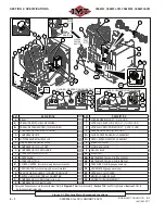
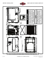
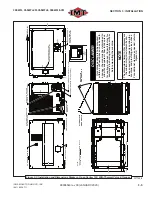
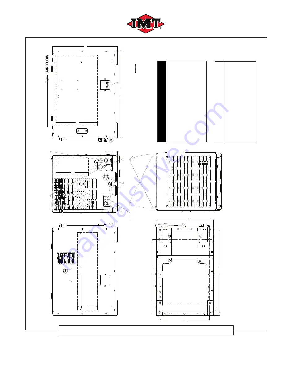
Figure 3-1: Installation and Dimensions Diagram - Open Center 12VDC
051665ID_r0
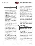
DISCLAIMER
If machine package is to be mount- ed within a con
fi
ned space such as
beneath a canopy
, the area must be
determined to allow for adequate air
fl
ow to take place for cooling purpos-
es. Consult factory for assistance
in ensuring adequate air
fl
ow
before
mounting the machine.
NOTE
The dimensions listed in this diagram are the minimum required clearance distances needed for properly cooling
the machine, and providing service access. For additional clearances
needed, refer to
Figure 3-4
.
Summary of Contents for CAS40PL
Page 2: ...BLANK PAGE...
Page 81: ...BLANK PAGE...

