99906549 rev 00 (JANUARY-2020)
3 - 9
SECTION 3: INSTALLATION
IOWA MOLD TOOLING CO., INC.
(641) 923-3711
CAS40PL, CAS40PL-CW, CAS40PLE, CAS40PLE-CW
nection port panel end of the unit. This system is
o
ff
ered with 12V DC circuits.
3.5.6 HYDRAULIC SUPPLY CIRCUIT
Refer to the proper hydraulic
fl
ow schematic
drawing (
Section 7.20
or
7.21
) that mathces the
machine model build. It is recommended that the
compressor unit possesses a separate pump/
fl
ow/return hydraulic circuit to other hydrau-
lic equipment. This is to prevent the possibility
of pressure/
fl
ow drops that may occur if other
hydraulically-powered equipment is activated
during compressor operation, which may in turn,
cause the compressor to stall out. Alternatively,
use of a diverter valve will permit hydraulics to
power di
ff
erent equipment selectively.
3.5.7 ROUTING
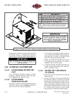
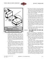
Refer to
Figure 3-1
or
Figure 3-2
, and the elec-
trical and wiring diagrams (
Sections 7.18
and
7.19
). Ensure that all supply hoses and electrical
wiring are correctly speci
fi
ed, adequately sup-
ported, and do not touch or rest on any sharp
edges. Wiring should be protected with split loom
to prevent corrosion, and consequently, loss due
to down time.
3.5.8 HYDRAULIC SYSTEM
REQUIREMENTS
Refer to
Sections 7.20
and
7.21
for hydraulic
system schematic layouts and components. The
following requirements should be taken into con-
sideration before installing the hydraulic system:
• The hydraulic
fl
ow and pressure requirements
of the air compressor.
• A continuous hydraulic load is necessary when
the compressor is running.
• The duty cycle and ambient operating tempera-
tures.
• Other hydraulic equipment which may share
the same hydraulic supply system (IMT rec-
ommends a dedicated pump and hydraulic
circuit).
3.6 CONNECTING
THE
HYDRAULIC SUPPLY AND
RETURN
Refer to
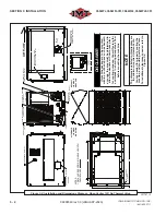
Figure 3-1
or
Figure 3-2
for hydraulic
supply and return hose location connections and
layout routing. Use correctly rated hoses (3000
PSI minimum) to securely connect both supply
(¾” J.I.C. 37° male) and return connectors (1”
J.I.C. 37° male).
NOTE
IMT recommends:
• SUPPLY HOSE: 3/4” J.I.C., 3000 PSI
• RETURN HOSE: 1” J.I.C., 500 PSI
• CASE DRAIN: 3/8” J.I.C., 500 PSI (load sense
1/4" JIC 3000 PSI; closed-center only)
3.7 CONNECTING
THE
AIR
SUPPLY
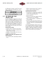
Refer to
Figure 3-1
or
Figure 3-2
for service
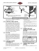
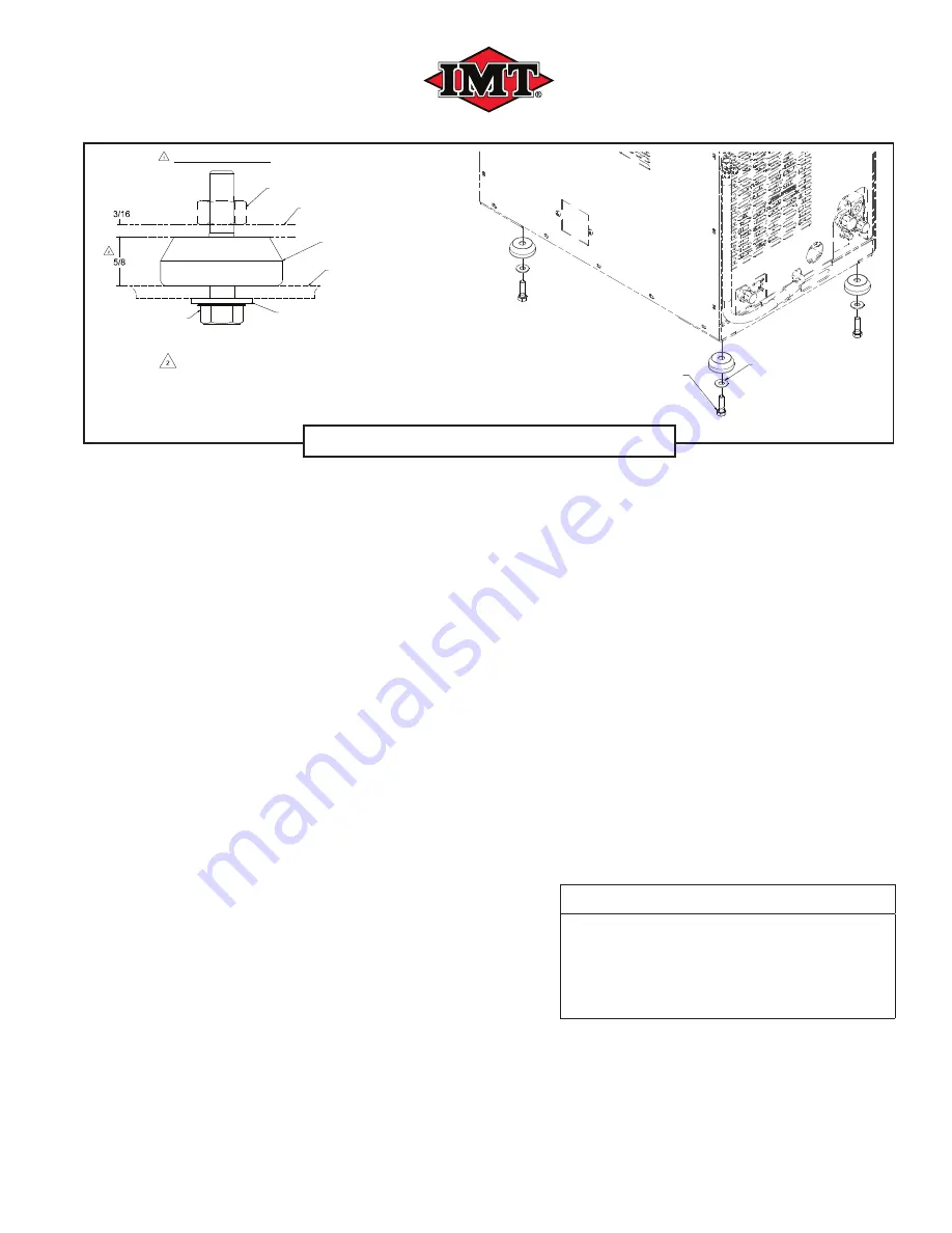
NOTES:
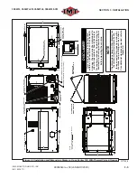
1. APPLY THREAD LOCKER TO HEX BOLTS BEFORE INSTALLATION
2. TIGHTEN BOLT UNTIL ISOLATOR IS COMPRESSED FROM NORMAL
EIGHT OF 1" TO FINAL HEIGHT OF 5/8"
Ø.50 FLAT (4X).
WASHER SUPPLIED
BY CUSTOMER
1/2-13 GR 8 HEX HEAD
CAPSCREW (4X)
LENGTH TO BE
DETERMINED AND
SUPPLIED BY
CUSTOMER
INSTALLED CONDITION
BUMPER
HEX HEAD
CAPSCREW
EXISTING WELDNUT
COMPRESSOR
FRAME
MOUNTING SURFACE
FLAT WASHER /
SEALING WASHER
Figure 3-5: Installation - Machine Isolator Mounting
280378_r2
Summary of Contents for CAS40PL
Page 2: ...BLANK PAGE...
Page 81: ...BLANK PAGE...


