SECTION 4:
OPERATION
99906549 rev 00 (JANUARY-2020)
4 - 1
SECTION 4: OPERATION
IOWA MOLD TOOLING CO., INC.
(641) 923-3711
CAS40PL, CAS40PL-CW, CAS40PLE, CAS40PLE-CW
4.1 GENERAL
INFORMATION
The IMT CAS40PL compressor has a compre-
hensive array of controls and indicators. Under-
standing the correct operation of the system will
help you to understand and recognize when it is
operating optimally. The information in the Oper-
ation Section will help the operator to recognize
and interpret the readings, which will call for ser-
vice or indicate the beginning of a malfunction.
4.2 OPERATING
CONDITIONS
1. Operate only in well-ventilated areas.
2. Ensure there are no obstructions of cooling
air intakes and outlets around the machine.
IMPORTANT
Be sure to leave su
ffi
cient room around the
machine for cooling air circulation during
operation. There must be a minimum of ten (10)
inches for the cooler intake, and ten (10) inches
for the sides and rear. Heated air must be able
to vent away from the intake.
3. Do not leave anything resting on top of the
machine. Hot cooling air will generate high
heat and must not be restricted.
4. Operate machine with the top cover closed.
5. Refer to speci
fi
cations for operating param-
eters.
6. Recommended:
DO NOT
exceed maximum
operating angle of 15°.
4.3 INITIAL
(FIRST-TIME)
START-UP
IMPORTANT
If start-up and shut-down procedures are not
followed, damage to the system and its compo-
nents may occur.
NOTE
Flow control needs to be set by the installer for
closed center units.
The compressor has been factory-tested and its
air and hydraulic valves have been adjusted to
their speci
fi
ed operating settings. The crankcase
has been factory-
fi
lled, but the oil needs to be
checked in order to ensure propper level before
initial start-up. Note also that vehilce needs to be
parked on level surface before checking the oil
level. Refer to
Section 5.4.3 Compressor Sys-
tem Lubrication
, for the correct lubricant type,
and sight glass and oil
fi
ll locations.
The following steps apply to the
fi
rst time start-up
after the machine installation. Check the oil, as
per the previous paragraph. Add oil if necessary.
Refer to
Figure 5-2
in
Section 5.4.3.1
for unit
check locations, and
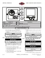
Figure 4-1
for instrumenta-
tion type, and
Figure 4-2
for Controller Screen
information (if applicable).
1. Ensure all service outlets are closed.
2. Ensure that the PTO ON/OFF switch is in the
ON position (fully engaged).
3. Apply hydraulic power.
4. Check for hydraulic supply or return leaks
and correct if required.
5. Allow air pressure to build up in the receiver
tank.
The compressor is now operating automatically.
It will continue to pump until the pressure reach-
es the factory set-point (100-175 psig). At this
point the compressor unit will switch o
ff
and the
hydraulic
fl
ow will be redirected back to the sup-
ply tank; any air in the compressor will be vented
to the atmosphere. The accumulated pressure
in the receiver tank is maintained by the check
valve
fi
tted to the compressor outlet connection.
For a closed center system, the solenoid valve
will be turned to the OFF position, causing the
load sense line to adjust the piston pump to pro-
vide less or no
fl
ow to prevent "Dead Heading"
Hydraulic Pressure.
When a demand is applied to the unit the receiver
tank pressure drops until it reaches the low pres-
sure set-point. The compressor then automatical-
ly restarts and repeats this cycle in response to
Summary of Contents for CAS40PL
Page 2: ...BLANK PAGE...
Page 81: ...BLANK PAGE...


