4 - 2
99906549 rev 00 (JANUARY-2020)
SECTION 4: OPERATION
IOWA MOLD TOOLING CO., INC.
(641) 923-3711
CAS40PL, CAS40PL-CW, CAS40PLE, CAS40PLE-CW
service demands and receiver tank pressure.
6. Move the PTO ON/ OFF switch to the OFF
position.
NOTE
Ensure that the service valve is closed and
compressor has stopped.
4.3.1 ROUTINE START-UP PROCEDURE
IMPORTANT
If start-up and shut-down procedures are not
followed, damage to the system and its compo-
nents may occur.
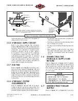
Refer to
Figure 5-2
in
Section 5.4.3.1
for unit
check locations, and
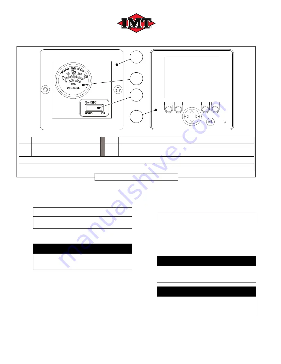
Figure 4-1
for instrumenta-
tion.
1. Ensure all service outlets are closed.
2. Ensure that the PTO ON/OFF switch is in the
ON position (fully engaged).
3. Apply hydraulic power.
4. Check for hydraulic supply or return leaks
and correct if required.
5. Allow air pressure to build up in the receiver
tank.
6. Move the PTO ON/ OFF switch to the OFF
position.
NOTE
Ensure that the service valve is closed and
compressor has stopped.
4.3.2 ROUTINE SHUTDOWN PROCEDURE
(FIRST AND ROUTINE)
IMPORTANT
If start-up and shut-down procedures are not
followed, damage to the system and its compo-
nents may occur.
IMPORTANT
Do not stop the engine suddenly! Stop the
engine after approximately
fi
ve (5) minutes of
unloaded idling.
1. Close service valve.
2. Allow compressor system to unload and cool
B
C
A
D
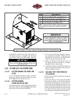
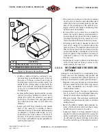
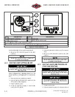
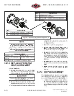
KEY
DESCRIPTION
KEY
DESCRIPTION
A
PNEUMATIC GAUGE PANEL
C
HOUR METER
B
PRESSURE GAUGE
D
DIGITAL DISPLAY CONTROLLER
I
I
Refer to
Figure 4-2
for digital controller identi
fi
cation and navigation.
Note that machine control panel option will be either
A
or
D
from the table above, depending upon order speci
fi
cation.
Figure 4-1: Instrumentation
Summary of Contents for CAS40PL
Page 2: ...BLANK PAGE...
Page 81: ...BLANK PAGE...

