background image

5 - 4


   99906549 rev 00 (JANUARY-2020)


SECTION 5: MAINTENANCE

IOWA MOLD TOOLING CO., INC.

(641) 923-3711

CAS40PL, CAS40PL-CW, CAS40PLE, CAS40PLE-CW

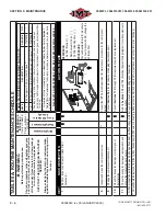
TABLE 5A: ROUTINE MAINTENANCE SCHEDULE

W

ARNING

Before performing maintenance: 

Shut down machine, relieve all system pressure  and lock out all power

, as per the Safety Section 

of this manual. If machine is hot, allow package 

to cool before removing any panel. 

NOTE THA

T THE SYSTEM CAN BE ST

ARTED 

REMOTEL

Y

:

Always clearly tag the start-up instrumentation  against accidental system start-ups during main-

tenance.

MAINTENANCE

INTER

V

ALS

Hourly or Calendar  Period - whichever 

comes 

fi

 rst

TABLE 5B: ROUTINE REPLACEMENT P

ARTS KITS 

*

KEY

 #

DESCRIPTION 

ORDER #

QTY

1

Kit, Compressor Service - Initial 50 Hours 

II

71417219

1

2

Kit, Compressor Lifetime W

arranty Service - 500 Hours 

II

71417220

1

*

 If working in dusty or dirty conditions, reduce the recommended time intervals between 

servicing by half for engine and compressor oil replacement, and engine and compressor 

fi

 lter 

servicing.

II

 For detailed kit content descriptions refer to 

Section 7, T

able 7A

. Also Refer to

 Section 7, 

Table 7A


for full replacement parts listing, including separate components, non-routine items, 

and options.

PLEASE NOTE: WHEN ORDERING P

ARTS, INDICA

TE MACHINE SERIAL

 NUMBER.

Daily Maintenance

Weekly Maintenance

Every 500 Hours or 

Annually

KEY

TASK DESCRIPTION

ACTION T

O

 T

AKE

7

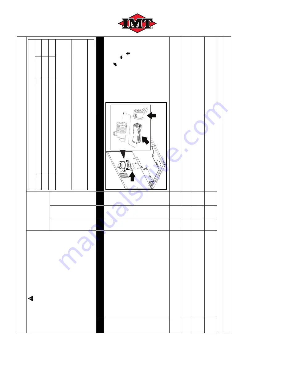
Remove, inspect, and clear air intake 

fi

 lter 

if 

necessary 

I

.

██

REFERENCE:

•  

Air Filter Element [

]

•  Dust Evacuator V

alve [

]

•  

Air Filter Housing Cover [

]

PROCEDURE: 

Consult


Section 5.4.4


for procedure 

on how to inspect and/or change the 

air intake 

fi

 lter

.

8

Inspect and clean the compressor valves.

II

Consult the IMT

 Service Department for maintenance procedure for the compressor 

valves.

9

Change the compressor crankcase oil.

Consult 

Section 5.4.3

 for procedure on changing the crankcase oil.

10

Check the hoses for damage or other signs of 

deterioration.

Consult 

Sections 7.13

 through

 7.16 

for assistance with hose replacement.

11

Check the wiring for damage or deterioration and 

ensure that connections are secure.

Refer to 

Sections 7.18 

and

 7.19

 (Electrical System Wiring Diagram) for wire system route 

connections.

I

 Air 

fi

 lters inspection performed weekly (change if needed); air 

fi

 lters change interval is yearly

, or sooner depending upon inspection.

II

 V

alves should be removed from the cylinder heads every 500 hours or annually (whichever comes 

fi

 rst) and examined for cleanliness and carbon formation (build-up).

Summary of Contents for CAS40PL

Page 1: ...and maintenance in structions in this manual will VOID THE EQUIPMENT WARRANTY NOTE This publication contains the latest information available at the time of preparation Every e ort has been made to en...

Page 2: ...BLANK PAGE...

Page 3: ...DECALS 1 3 1 5 DISPOSING OF MACHINE FLUIDS 1 3 SECTION 2 SPECIFICATIONS 2 2 Figure 2 1 Machine Main Component Locations 2 1 2 1 GENERAL INTRODUCTION 2 2 TABLE 2A SPECIFICATIONS 2 2 TABLE 2B CAPSCREW...

Page 4: ...4 RECOMMENDED RESERVOIR OPTIONS 3 7 3 4 2 5 RESERVOIR FEATURES TO AVOID 3 8 3 4 2 6 RECOMMENDED HYDRAULIC SYSTEM SPECIFICATIONS 3 8 3 4 3 STANDARDS GUIDELINES 3 8 3 5 INSTALLATION 3 8 3 5 1 MACHINE LO...

Page 5: ...LACEMENT KITS 5 3 5 4 PARTS REPLACEMENT AND ADJUSTMENT PROCEDURES 5 5 5 4 1 REMOVING PANELS FOR MACHINE MAINTENANCE ACCESS 5 5 5 4 1 1 REMOVING LONG SIDE PANELS FOR MAINTENANCE ACCESS 5 5 5 4 1 2 REPL...

Page 6: ...CONTROL 7 8 7 6 MOTOR AND DRIVE PARTS 7 9 7 7 HYDRAULIC COOLER PARTS 12V WITH THRML GAUGES 7 10 7 8 HYDRAULIC COOLER PARTS 24V WITH THRML GAUGES 7 12 7 9 FRAME AND CANOPY 1 OF 3 ASSEMBLY PART A 7 14 7...

Page 7: ...ILLUSTRATED PARTS LIST CONTINUED 7 17 HYDRAULIC THERMAL VALVE ASSEMBLY 7 28 7 18 ELECTRICAL SCHEMATIC 7 29 7 19 WIRING DIAGRAM 7 30 7 20 HYDRAULIC OIL FLOW SCHEMATIC DIAGRAM OPEN CENTER WITH THERMAL V...

Page 8: ...TOC VI 99906549 rev 00 JANUARY 2020 TABLE OF CONTENTS IOWA MOLD TOOLING CO INC 641 923 3711 CAS40PL CAS40PL CW CAS40PLE CAS40PLE CW BLANK PAGE...

Page 9: ...severe injury or equipment damage or destructive malfunctions Keep tools or other conductive objects away from live electrical parts Never touch electrical wires or components while the machine is ope...

Page 10: ...icable codes Pressurized broken or disconnected hoses can whip causing injuries or damage DO NOT use tools hoses or equipment that have maximum ratings below that of this com pressor Keep metal tools...

Page 11: ...box titled with an IMPORTANT banner as shown below and may also contain the WARNING symbol should the information be linked to a safety issue IMPORTANT Additional CRUCIAL information or existing infor...

Page 12: ...PRESSOR OIL DRAIN HOSE Z RELIEF VALVE J COOLER FAN FAN MOTOR AA SOLENOID K CONTROLLER BB1 INSTRUMENT PANEL DIGITAL DISPLAY L HYDRAULIC MOTOR BB2 INSTRUMENT PANEL GAUGE DISPLAY M1 CLOSED CENTER functio...

Page 13: ...0 2575 2600 2300 2470 2550 2600 NOTE Compressor adjustment should be set in accordance with rated RPMs I 30 CFM 690 COMPRESSOR RPM II 40 CFM 1100 COMPRESSOR RPM COMPRESSOR GENERAL SYSTEM INFORMATION S...

Page 14: ...omatic load control 12 or 24V Air pressure switch for automatic load control Pre set at factory TABLE 2B CAPSCREW TIGHTENING TORQUE VALUES SIZE GRADE LUBRICATED 1 4 20 UNC 5 6 ft bs 5 16 18 UNC 5 13 f...

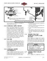
Page 15: ...such as electrical and hydraulic power supply availability and location DISCLAIMER DO NOT install in any enclosed space without first contacting IMT WARNING Install operate and maintain this equipmen...

Page 16: ...EW IMPORTANT IMT highly recommends consulting a hydraulic supply expert for specifying the correct hydrau lic supply components for vehicle side integra tion including oil reservoir size hydraulic pre...

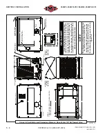
Page 17: ...17 12 09 6 54 7 45 1 2 13 UNC NU T 8 PLACES 3 51 23 48 21 25 1 00 30 50 18 44 NOTES 1 DECAL AREA SHOWN IN DASHED LINES Figure 3 1 Installation and Dimensions Diagram Open Center 12VDC 051665ID_r0 DISC...

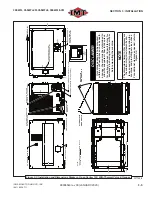
Page 18: ...OWN IN SINGLE LENGTH DASHED LINES PRESSURE GAUGE HOUR METER OR CONTROLLER DISPLAY 1 2 13 UNC NUT 8 PLACES Figure 3 2 Installation and Dimensions Diagram Open Center 12V No Thermal Valve 051787_r2 DISC...

Page 19: ...ALTERNATE LID HINGE DIRECTION 21 00 3 51 23 48 18 44 1 40 1 00 1 2 13 UNC NUT 8 PLACES 30 50 NOTES 1 DECAL AREA SHOWN IN SINGLE LENGTH DASHED LINES Figure 3 3 Installation and Dimensions Diagram Open...

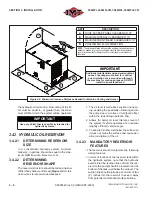
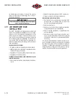
Page 20: ...turn flow well below the surface so it does not break the surface and cause aer ation cavitation of the oil 3 4 2 3 MANDATORY RESERVOIR FEATURES The reservoir should incorporate the following design f...

Page 21: ...e is needed to protect the system against contaminants be ing introduced into the oil The filter should be mounted externally from the reservoir in a lo cation that allows for easy of service access A...

Page 22: ...ne so that there is no restriction of cooling air through the enclosure Refer to Figure 3 3 Cooling air enters the en closure at the rear cooler package end of the machine passes through the cooler an...

Page 23: ...stem schematic layouts and components The following requirements should be taken into con sideration before installing the hydraulic system The hydraulic flow and pressure requirements of the air comp...

Page 24: ...pliant to applicable stan dards 200 psig minimum Supplied with an adequately rated relief valve Supplied with moisture drain CONNECTION HOSING AND SERVICE VALVE SPECIFICATIONS Hose must be flexible st...

Page 25: ...ified operating settings The crankcase has been factory filled but the oil needs to be checked in order to ensure propper level before initial start up Note also that vehilce needs to be parked on lev...

Page 26: ...ly or return leaks and correct if required 5 Allow air pressure to build up in the receiver tank 6 Move the PTO ON OFF switch to the OFF position NOTE Ensure that the service valve is closed and compr...

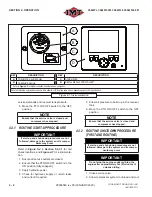
Page 27: ...his screen shows the preset cut in and cut out pressures for the range of operation These pres sures can be adjusted by pressing the Up or Down arrows Note that when adjusting the Cut in Cut out press...

Page 28: ...utes 3 Shut o hydraulic power supply 4 4 EXTREME CONDITION OPERATION When operating in extreme hot or cold conditions extra attention should be given to any indications that could lead to a serious pr...

Page 29: ...ment while it is operating WARNING DO NOT touch electrical wires wire harnesses terminals or other components when power is applied to the compressor unit WARNING Keep metal tools and other conductive...

Page 30: ...ne maintenance or replacement parts consult Section 7 1 Parts Ordering Pro cedure and Table 7A Recommended Spare Parts List 5 3 REPLACEMENT PARTS Replacement parts should be purchased through your loc...

Page 31: ...e 7A for full replacement parts listing including separate components non routine items and options PLEASE NOTE WHEN ORDERING PARTS INDICATE MACHINE SERIAL NUMBER Daily Maintenance Weekly Maintenance...

Page 32: ...ing including separate components non routine items and options PLEASE NOTE WHEN ORDERING PARTS INDICATE MACHINE SERIAL NUMBER Daily Maintenance Weekly Maintenance Every 500 Hours or Annually KEY TASK...

Page 33: ...ent clean when performing maintenance or service actions Cover open ings to prevent contamination NOTE When using compressed air to clean the com ponents the nozzle pressure should not exceed 15 PSIG...

Page 34: ...cting the oil level ensure that the oil fill sight glass does not contain any cracks or pits The compressor is fully charged at the facto ry with IMT Reciprocating Compressor Oil This section gives de...

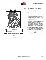
Page 35: ...ately every 500 operating hours or sooner depending upon inspection Plugged air filters can cause high oil consumption and reduced delivery quantity Change the filter more often when running in dusty...

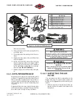
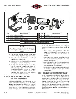
Page 36: ...nt element available within kit no 71417220 Once obtained refer to Figure 5 3 and the following procedure to service the air filter 1 Review the safety guidelines in Section 5 4 4 then follow steps 1...

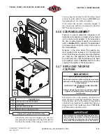
Page 37: ...ring the motor to the unit via the motor adapter However in the case where the coupling ele ment needed to be replaced or if the alignment is such that there is excessive machine vibration etc there i...

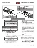
Page 38: ...oupling assembly 4 Remove the spider coupling element 5 Carefully wipe the coupling halves with a clean cloth and place the new element into position on the compressor coupling half 6 Re insert the mo...

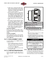
Page 39: ...Figure 5 6 5 4 7 3 HUB ALIGNMENT CHECK To ensure alignment refer to Figure 5 6 and the following procedure 1 Place a straight edge square on the outer di ameter of both halves in locations 90 apart T...

Page 40: ...always be aware of the safety warnings given in Section 1 Safety WARNING Before performing maintenance Shut down machine relieve all system pres sure and lock out all power as per the Safety Section o...

Page 41: ...ain valve on the tank Cover with a waterproof secured tarp or plastic sheet to prevent the accumulation of dust but leave the bottom open for air circulation The covering should allow for easy removal...

Page 42: ...5 14 99906549 rev 00 JANUARY 2020 SECTION 5 MAINTENANCE IOWA MOLD TOOLING CO INC 641 923 3711 CAS40PL CAS40PL CW CAS40PLE CAS40PLE CW BLANK PAGE...

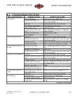
Page 43: ...The procedures which can be performed in the least amount of time and with the least amount of re moval or disassembly of parts should be per formed first Always remember to 1 Check for loose wiring 2...

Page 44: ...ion 7 18 and 7 19 Low hydraulic flow pressure Check and reset Refer to Sections 7 11 and 7 12 for flow regulator location and replacement info Hydraulic motor or pump worn Replace Low hydraulic oil le...

Page 45: ...relief valve s open con tinuously Defective air pressure gauge Refer to Section 5 4 2 and Section 7 5 Replace if neces sary Damaged worn or leaking valve Replace valve Pressure switch set too high Ma...

Page 46: ...r Worn piston rings Replace rings Piston rings incorrectly installed Reinstall Worn or scored cylinder Replace cylinder and rings Knocking sound from compressor Crankcase oil level low Check refill to...

Page 47: ...ct the factory directly at the address or phone numbers below When ordering parts always indicate the Serial Number of the machine package This can be obtained form the Bill of Lading for the machine...

Page 48: ...f 65 PSI low pressure 71417228 1 13 Valve Relief 200 PSI high pressure 73540467 1 14 Element Drive Coupling Replacement 71417229 1 15 Kit Isolator 71417230 1 16 Valve Solenoid Replacement IV 1 17 Regl...

Page 49: ...ide to replacement parts damage may occur to the machine beyond the scope of this listing Should any part of the compressor package that is not listed in Table 7A become damaged or inoperable use the...

Page 50: ...RICATE ALL ELASTOMERIC SEALS GASKETS O RINGS BEFORE TIGHTENING 3 ALL BOLTS TO BE TORQUED TO THEIR RESPECTIVE SAE TORQUE SPECIFICATIONS FOR THEIR GRADES AND SIZES UNLESS OTHERWISE SPECIFIED HIGH PRESSU...

Page 51: ...EE 1 4 NPT MALE BRANCH 1 4 ORIFICE FILTER 032 DIA 1 4 FPT X 1 4 MPT 1 5 WASHER LOCK 1 2 GRADE 8 4 6 VALVE CHECK MANIFOLD 60CFM 450F 1 7 COMPRESSOR PARTS DD AL 1 8 EYE LIFTING COMPRESSOR 1 9 HOSE COMPR...

Page 52: ...ED PARTS LIST 7 6 99906549 rev 00 JANUARY 2020 CAS40PL CAS40PL CW CAS40PLE CAS40PLE CW IOWA MOLD TOOLING CO INC 641 923 3711 PRESSURE RELIEF 200 TO 217 PSIG 15 BAR PRESSURE RELIEF 65 PSIG 7 3 COMPRESS...

Page 53: ...N559 1 14 TUBE MID STAGE COOLING 1 5 HOUSING BELL HYD MOTOR TO COMPRESSOR 1 15 GASKET DISCHARGE AFTERCOOLER 1 6 HUB COUPLING COMPRESSOR DD 1 16 VALVE RELIEF 65 PSI 1 4 NPT MALE 1 7 SPIDER COUPLING DD...

Page 54: ...IC 1 6 PANEL GAUGE ELECTRONIC REAR 1 PLEASE NOTE WHEN ORDERING PARTS INDICATE MACHINE SERIAL NUMBER POS AND NEG ARE INTERCHANGEABLE NOTES 1 USE LOCTITE 567 THREAD SEALANT WITH PTFE OR EQUIVALENT SEALA...

Page 55: ...T SCREW SUPPLIED WITH COMPRESSOR ASSEMBLY 7 6 MOTOR AND DRIVE PARTS 6100242ID_r1 ITEM DESCRIPTION PART NUMBER QTY 1 ELBOW 90 DEG 8 MJIC x 12 MSAE 1 2 ELBOW 90 DEG 4 MJIC x 6 MSAE 1 3 TEE JIC JIC SAE 1...

Page 56: ...RAME CANOPY DRAWING 6020235 12V W THRML SHOWN TABULATED ASSEMBLIES PART NUMBER DESCRIPTION ITEM A DESCRIPTION ITEM B DESCRIPTION ITEM C DESCRIPTION HYDRAULIC COOLER PARTS 12V W THRML RELAY NO NC WEATH...

Page 57: ...T SENSOR MOUNTING 1 5 BRACKET COOLER MOUNTING LEFT 1 6 KIT ACOUSTICAL INSULATION 2 7 BUSHING PIPE BRASS 1 4 x 1 8 1 8 NUT HEX FLANGE 1 4 20 2 9 NUT HEX FLANGE 5 16 18 6 10 NUT HEX LOCKING 5 16 18 4 11...

Page 58: ...LR PRTS 12V W THRML GAUGES RELAY NO NC WHTRPRF 12V w BKT RSTR TEE MJIC MJIC ORNG RUN 3 4 CLR OIL ASSY HYD CLR PRTS 24V W THRML GAUGES RELAY NO NC 24V WHTRPRF 20 AMP TEE MJIC MJIC ORNG RUN 3 4 CLR OIL...

Page 59: ...1 4 NPT 1 5 BRACKET COOLER MOUNTING RIGHT 1 6 BRACKET SENSOR MOUNTING 1 7 BRACKET COOLER MOUNTING LEFT 1 8 KIT ACOUSTICAL INSULATION 2 9 ELBOW PIPE STREET 1 4 1 10 NUT HEX FLANGE 1 4 20 3 11 NUT HEX F...

Page 60: ...99906549 rev 00 JANUARY 2020 CAS40PL CAS40PL CW CAS40PLE CAS40PLE CW IOWA MOLD TOOLING CO INC 641 923 3711 NOTE THIS END TO LID FASTEN WITH BLUE LOCTITE ZIP TIE HARNESS HERE 7 9 FRAME AND CANOPY 1 OF...

Page 61: ...SPACER 313ID X 0 75OD X 0 375L 2 2 WASHER NYLON FLAT 1 4 22 3 SCREW TRUSS 1 4 20 X 3 4 SS 22 4 GAS SPRING 6 STROKE 20 1 5 CAPSCREW HEX GR5 1 4 20 x 0 75 3 6 CAPSCREW HEX GR5 1 4 20 x 1 2 7 SCREW SER...

Page 62: ...ASKET SEAL AND TRIM 1 333 ft PLEASE NOTE WHEN ORDERING PARTS INDICATE MACHINE SERIAL NUMBER INSTALL FOR MODELS USING MECHANICAL GAUGES ONLY 2x DEFAULT INSTRUMENT PANEL LOCATION 2x 2x 4x 4x 2x ITEM DES...

Page 63: ...3 4 1 PLEASE NOTE WHEN ORDERING PARTS INDICATE MACHINE SERIAL NUMBER ITEM DESCRIPTION PART NUMBER QTY 1 PANEL COOLER SIDE 1 2 KIT ACOUSTICAL INSULATION 1 3 NUT HEX LOCKING 5 16 18 UNC 1 4 STUD BALL 39...

Page 64: ...3 3711 NOTES 1 LUBRICATE ALL ELASTOMERIC SEALS GASKETS O RINGS BEFORE TIGHTENING 2 ALL BOLTS TO BE TORQUED TO THEIR RESPECTIVE SAE TORQUE SPECIFICATIONS FOR THEIR GRADES AND SIZES UNLESS OTHER WISE SP...

Page 65: ...DRAULIC SOFT SHIFT 1 6 CAP FEMALE JIC SHIPPING 6 9 16 18 1 7 CAP FEMALE JIC SHIPPING 12 1 1 16 12 1 8 CAP FEMALE JIC SHIPPING 16 1 5 16 12 1 9 BRACKET HYD OIL OP CTR MNFLD 1 10 NUT HEX LOCKING 3 8 16...

Page 66: ...SEALS GASKETS O RINGS BEFORE TIGHTENING 2 ALL BOLTS TO BE TORQUED TO THEIR RESPECTIVE SAE TORQUE SPECIFICATIONS FOR THEIR GRADES AND SIZES UNLESS OTHERWISE SPECIFIED 3 ADD DROPS OF RED LOCTITE TO ALL...

Page 67: ...SHIPPING 6 9 16 18 279109 002 1 8 CAP FEMALE JIC SHIPPING 12 1 1 16 12 279109 005 1 9 CAP FEMALE JIC SHIPPING 16 1 5 16 12 279109 006 1 10 BRACKET HYD OIL CLSD CTR MNFLD 279469 1 11 NUT HEX LOCKING 5...

Page 68: ...R HOSE I 1 5 DECAL IMT SERVICE REPAIR 70392962 1 6 DECAL CAUTION AUTO START I 1 7 DECAL HYDRAULIC HIGH PRESSURE I 1 8 DECAL DO NOT REMOVE CAPS I 1 9 DECAL DO NOT USE AIR I 1 11 DECAL IMT OIL RECIPROCA...

Page 69: ...l that becomes damaged or illegible ITEM DESCRIPTION PART NUMBER QTY 13 DECAL LOGO IMT CAS40PL I 2 14 DECAL AIR DISCHARGE 1 15 DECAL 12VDC 1 16 DECAL HYDRAULIC RETURN 1 17 DECAL HYDRAULIC CASE DRAIN 1...

Page 70: ...AND TUBE ROUTING INSTRUCTIONS ITEM PART NUMBER DESCRIPTION QTY START END 1 HOSE HYDRAULIC MOTOR IN DD 1 A A 2 HOSE HYDRAULIC MANF TO MOTOR OUT DD 1 B B 3 HOSE HYDRAULIC MOTOR TO COOLER DD 1 C C 4 HOSE...

Page 71: ...SCRIPTION QTY START END 1 HOSE HYDRAULIC MOTOR IN DD 1 A A 2 HOSE HYDRAULIC MANF TO MOTOR OUT DD 1 B B 3 HOSE HYDRAULIC COOLER OUT 1 C C 3 HOSE HYDRAULIC MOTOR CASE DRAIN DD 1 D D 5 HOSE HYDR MOTOR TO...

Page 72: ...NSTRUCTIONS ITEM PART NUMBER DESCRIPTION QTY START END 1 HOSE HYDRAULIC MOTOR IN DD 1 A A 2 HOSE HYDRAULIC MANF TO MOTOR OUT DD 1 B B 3 HOSE HYDRAULIC MOTOR TO COOLER DD 1 C C 4 HOSE HYDRAULIC COOLER...

Page 73: ...N QTY START END 1 HOSE HYDRAULIC MOTOR IN DD 1 A A 2 HOSE HYDRAULIC MANF TO MOTOR OUT DD 1 B B 3 HOSE HYDRAULIC COOLER OUT 1 C C 3 HOSE HYDRAULIC MOTOR CASE DRAIN DD 1 D D 5 HOSE HYDR MOTOR TO THERM V...

Page 74: ...923 3711 7 17 HYDRAULIC THERMAL VALVE ASSEMBLY ITEM DESCRIPTION PART NUMBER QTY 1 ELBOW 90 DEG 12 MJIC x 16 MSAE 3 2 VALVE THERMAL BYPASS 1 SAE 50PSI 100 DEG 1 PLEASE NOTE WHEN ORDERING PARTS INDICAT...

Page 75: ...OF KEYED IGNITION C VBBS IN8 IN9 GND GND IN10 IN11 VBBS E OUT0 GND OUT1 GND OUT2 GND OUT3 GND N2 VBBS CAN2H CAN2L GND HMI 60 OHM RESISTOR FUSE 3 2 30 AMP JCASE STYLE FUSE VANAIR 279301 FOR 12V AND 24V...

Page 76: ...CONNECTED TO A TERMINAL ON CONNECTOR 17 5 HOUR METER 14 4 7 16 PRESS URE SWITCH 6 PIN CONNECTOR 9 6 30 87 N O 87A N C 85 86 SAFETY RELAY NC NO C 1 2 4 N G 20 21 3A 19 12 15 8 16A MANIFOLD BLOCK VALVE...

Page 77: ...RAULIC OIL COOLER DIRECTION HYDRAULIC OIL ROTATION RESERVOIR PUMP TRUCK SYSTEM FILTER PRESSURE RETURN MACHINE END PANEL THERMAL VALVE W PRESSURE RELIEF IN COOLER TANK CASE DRAIN SOLENOID RELIEF VALVE...

Page 78: ...OLD TOOLING CO INC 641 923 3711 HYDRAULIC OIL COOLER RELIEF VALVE ROTATION RESERVOIR PUMP TRUCK SYSTEM FILTER PRESSURE RETURN MACHINE END PANEL SOLENOID VALVE CASE DRAIN P T A B TRUCK SYSTEM MACHINE H...

Page 79: ...e motion produces bending rather than twisting 4 Use elbows or other adapters as necessary to eliminate excess hose length and to insure neater installation for easier main tenance 2 Ample bend radius...

Page 80: ...USTRATED PARTS LIST 7 34 99906549 rev 00 JANUARY 2020 CAS40PL CAS40PL CW CAS40PLE CAS40PLE CW IOWA MOLD TOOLING CO INC 641 923 3711 TABLE 7B MAINTENANCE TRACKING LOG DATE DESCRIPTION OF MAINTENANCE PA...

Page 81: ...BLANK PAGE...

Page 82: ...oling Co Inc 500 Highway 18 West Garner Iowa 50438 Phone 641 923 3711 Fax 641 923 2424 www imt com 051731 051829 051830 051831 Printed in the U S A Specifi cations subject to change without prior noti...

Reviews: