99906549 rev 00 (JANUARY-2020)
5 - 5
SECTION 5: MAINTENANCE
IOWA MOLD TOOLING CO., INC.
(641) 923-3711
CAS40PL, CAS40PL-CW, CAS40PLE, CAS40PLE-CW
5.4 PARTS
REPLACEMENT
AND
ADJUSTMENT PROCEDURES
WARNING
Follow all applicable safety recommendations
as outlined in Section 1: Safety of this manual.
WARNING
Before performing maintenance:
Shut down machine, relieve all system pressure
and lock out all power, as per the Safety Section
of this manual. If machine is hot, allow package
to cool before removing any panel.
NOTE THAT THE SYSTEM CAN BE STARTED
REMOTELY:
Always clearly tag the start-up instrumentation
against accidental system start-ups during
maintenance.
WARNING
DO NOT use tools, hoses, or equipment that
have maximum ratings below that of this com-
pressor.
WARNING
DO NOT use
fl
ammable solvents or cleaners for
cleaning the compressor or its parts.
NOTE
Wear appropriate protective (eye and hear-
ing protection) equipment and clothing when
operating or maintaining this equipment. DO
NOT wear jewelry, loose clothing; and long hair
should be restrained with headband or safety
hat.
NOTE
Keep the equipment clean when performing
maintenance or service actions. Cover open-
ings to prevent contamination.
NOTE
When using compressed air to clean the com-
ponents, the nozzle pressure should not exceed
15 PSIG.
5.4.1 REMOVING PANELS FOR MA-
CHINE MAINTENANCE ACCESS
Although most of the routine maintenance proce-
dures can be accessed from either outside of the
compressor package or via the top roof access
panel, some procedures will require the tempo-
rary removal of one or both side panels in order to
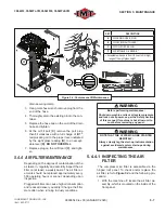
freely service the maintenance item. Consult
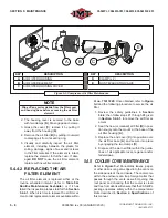
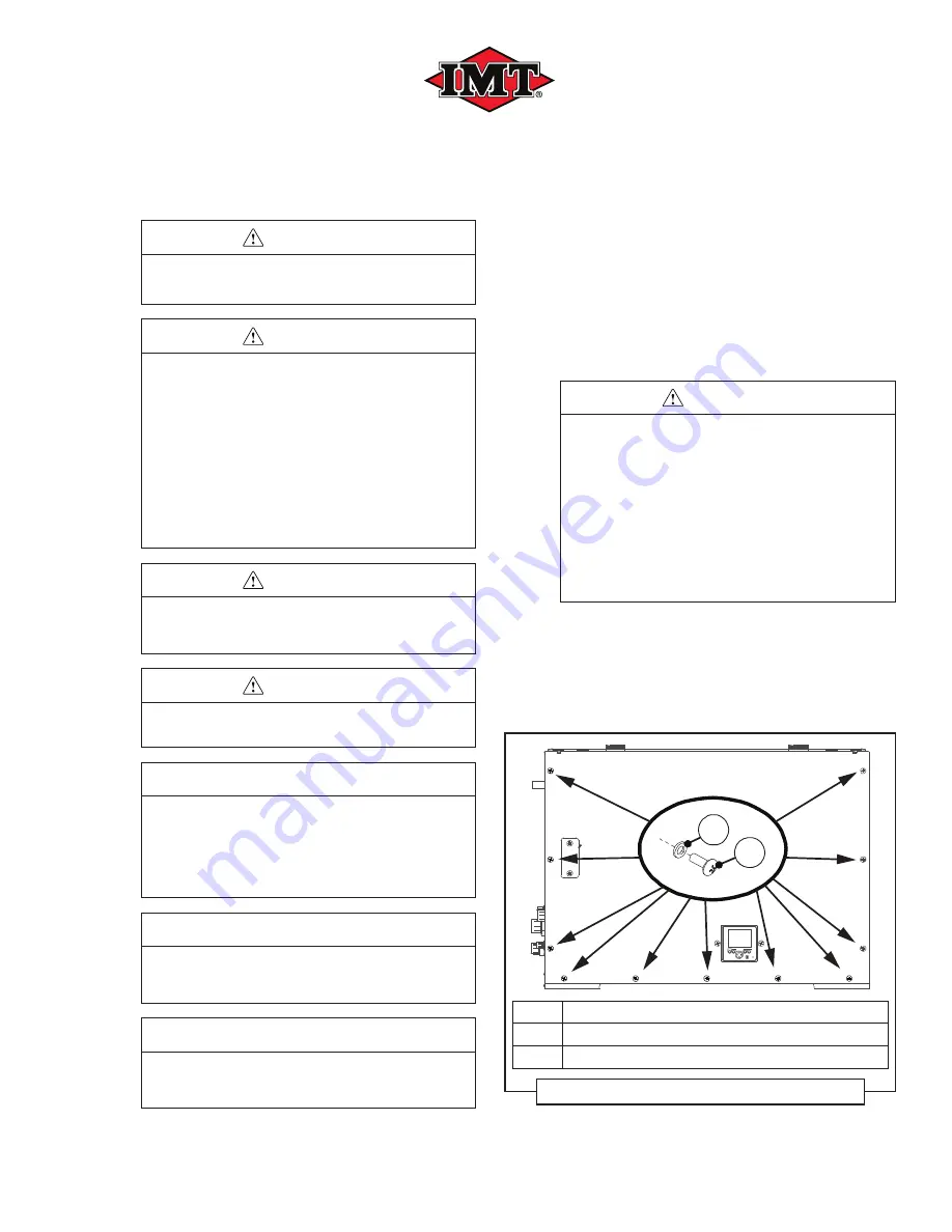
Fig-
ure 5-1
and the proper panel removal sub-sec-
tion listed below to remove the desired panel.
WARNING
Before performing maintenance:
Shut down machine, relieve all system pressure
and lock out all power, as per the Safety Section
of this manual. If machine is hot, allow package
to cool before removing any panel.
NOTE THAT THE SYSTEM CAN BE STARTED
REMOTELY:
Always clearly tag the start-up instrumentation
against accidental system start-ups during
maintenance.
5.4.1.1 REMOVING LONG-SIDE PANELS
FOR MAINTENANCE ACCESS
Consult
Figure 5-1
and the following procedures
to remove a side panel for maintenance access.
A
B
KEY
DESCRIPTION
A
TRUSS SCREW, 1/4-20 X 3/4” (X 11 each/side panel)
B
WASHER, NYLON FLAT 1/4” (X 11 each/side panel)
Figure 5-1: Panel Removal
Summary of Contents for CAS40PL
Page 2: ...BLANK PAGE...
Page 81: ...BLANK PAGE...

