5 - 10
99906549 rev 00 (JANUARY-2020)
SECTION 5: MAINTENANCE
IOWA MOLD TOOLING CO., INC.
(641) 923-3711
CAS40PL, CAS40PL-CW, CAS40PLE, CAS40PLE-CW
NOTE
Alignment checks should not be necessary,
as the machine is factory-set. However, when
performing a coupling element replacement,
proper sizing and o
ff
set measurements must be
properly set and checked to avoid damage to
machine and/or coupling.
TOOLS REQUIRED
TORQUE WRENCH
ALLEN SOCKETS
MEDIUM STRENGTH REMOVABLE
LOCTITE
®
CALIPERS / FEELER GAUGES
ALIGNMENT TOOLS (i.e, straight edge, dial indicator, shims, etc).
5.4.7.1 REPLACING THE DRIVE
COUPLING ELEMENT
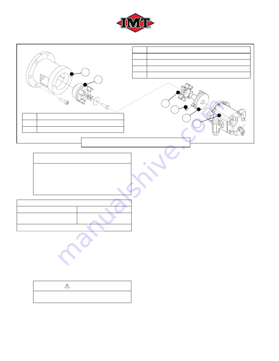
Refer to
Figure 5-5
.
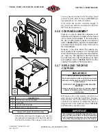
1. Remove the screw from the coupling cover
and slide cover away from the compressor
unit to access the drive coupling assembly.
CAUTION
Cover will be under spring tension; use care
when removing the cover.
2. Remove the two capscrews and lock wash-
ers that secure the motor to the motor mount.
3. Carefully extract the motor from the mount,
pulling directly outward; this will separate the
coupling assembly.
4. Remove the spider coupling element.
5. Carefully wipe the coupling halves with a
clean cloth, and place the new element into
position on the compressor coupling half.
6. Re-insert the motor with the motor-side cou-
pling half to mate with the coupling element
and compressor coupling half. Note that the
motor coupling may need to be rotated slight-
ly by hand to achieve coupling and element
alignment.
7. Re-install the two 3/8” capscrews and lock
washer sets to secure the motor to the motor
mount.
8. Before torquing the bolts, perform an align-
ment check on the hubs (refer to
Section
5.4.7.3
).
5.4.7.2 COUPLING ASSEMBLY
The following method is used for a full re-instal-
lation of a drive coupling system. For performing
an element change only, refer to
Section 5.4.7.1
.
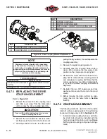
1. Install and mate coupling hub bore with driv-
ing shaft. Hub should be installed with the
hub body toward the driving unit (see
Figure
5-5
for typical mounting component arrange-
ment).
B
E
F
D
A
C
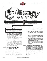
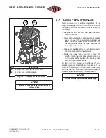
Figure 5-5: Drive Coupling Element Replacement
KEY
DESCRIPTION
A
COMPRESSOR UNIT BELL HOUSING
B
COMPRESSOR COUPLING HUB
KEY
DESCRIPTION
C
SPIDER COUPLING
D
MOTOR COUPLING HUB
E
SET SCREW FOR MOTOR COUPLING HUB
F
MOTOR
Summary of Contents for CAS40PL
Page 2: ...BLANK PAGE...
Page 81: ...BLANK PAGE...

