99906549 rev 00 (JANUARY-2020)
3 - 7
SECTION 3: INSTALLATION
IOWA MOLD TOOLING CO., INC.
(641) 923-3711
CAS40PL, CAS40PL-CW, CAS40PLE, CAS40PLE-CW
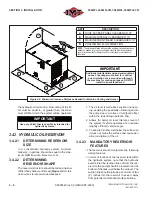
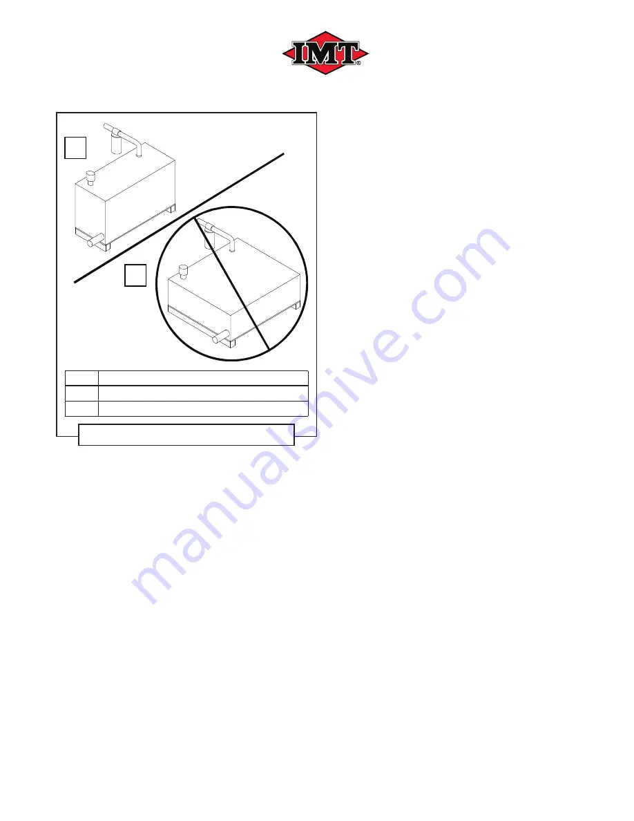
A
B
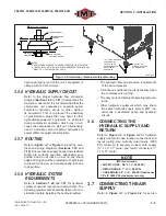
KEY
DESCRIPTION
A
PREFERRED SHAPE:
TALL AND NARROW
B
SHAPE TO AVOID:
BROAD AND SHALLOW
Figure 3-4: Reservoir Design Shape
• A ba
ffl
e or ba
ffl
es should be included to pre-
vent sloshing, or centrifugal motion of the oil;
the goal is to break up direct
fl
ow of the oil
from the return point to the suction point. This
allows for the cooling action contact with the
tanks’ inner surfaces, and promote separation
of any air or contaminants that interact with
the
fl
owing oil.
• An ideal ba
ffl
e design would position several
(but not too many) ba
ffl
es to promote an ‘S’
shape
fl
ow within the reservoir, as viewed
from above. The area of the end gaps should
be at least twice the area of the suction line
diameter.
• A drain port with plug, situated at the lowest
point of the reservoir, is needed to assure
complete draining. It should be installed using
an adapter or housing which does not pro-
trude above the inner surface of the
fl
oor of
the tank. It should be visible and accessible
for removal, with su
ffi
cient space available for
catching the waste oil.
• If the return line entrance to the tank is located
near the top, it should be extended downward
within the tank to minimize foaming and aer-
ation of the circulating oil. This extends oil in-
tegrity, which in turn helps to maintain system
performance and reliability.
• An in-line
fi
lter on the return line is needed to
protect the system against contaminants be-
ing introduced into the oil. The
fi
lter should be
mounted externally from the reservoir in a lo-
cation that allows for easy of service access.
• A breather and
fi
ll cap is needed at the oil
fi
ll
port, which needs to be located above the
system oil level. The breather cap acts to both
fi
lter air that is drawn into the reservoir as the
oil level diminishes, and bleeds air out as the
level is regained. This maintains constant at-
mospheric pressure in the air volume within
the reservoir.
• A sight-glass provides a direct visual indication
of the oil level without having to open, or oth-
erwise access, the reservoir.
3.4.2.4 RECOMMENDED
RESERVOIR
OPTIONS
Although not essential for an adequately func-
tioning reservoir, the following components will
contribute to maximize the hydraulic system’s ef-
fi
ciency and maintain a quality operational level.
• Magnetic drain plug: Attracts and concentrates
ferrous contaminants at the drain plug source
for easier accessibility and removal when
cleaning tank interior.
• A temperature gauge: Located in approxima-
tion to, or built in to, the sight glass assembly
allows for temperature reading at a glance.
• Filler port strainer: Prevents large contaminant
particles from blending with system oil when
adding new oil.
• Return line di
ff
user (splash) plate reduces ve-
locity of oil
fl
ow before return oil stream merg-
es with the main reservoir oil volume.
• A reservoir heater: For those systems that are
exposed to cold climate ambients, having the
ability to preheat the hydraulic oil prior to start
up will make for easier startups, and reduce
the strain of warming up the system under ad-
Summary of Contents for CAS40PL
Page 2: ...BLANK PAGE...
Page 81: ...BLANK PAGE...

