3 - 8
99906549 rev 00 (JANUARY-2020)
SECTION 3: INSTALLATION
IOWA MOLD TOOLING CO., INC.
(641) 923-3711
CAS40PL, CAS40PL-CW, CAS40PLE, CAS40PLE-CW
verse cold conditions.
3.4.2.5 RESERVOIR FEATURES TO
AVOID
A strainer used to screen the suction line is not
recommended for systems designed for mobile
equipment use. Having equipment that likely ex-
periences long suction lines, cold startups and
non-tracked or infrequent maintenance practic-
es may cause this strainer to potentially promote
system strain (cavitation) than prolong
fl
uid integ-
rity through
fi
ltration.
A pressurized reservoir is not recommended for
vehicles, as its complexity invites too much po-
tential for loss of system reliability if it is not prop-
erly maintained.
3.4.2.6 RECOMMENDED
HYDRAULIC
SYSTEM SPECIFICATIONS
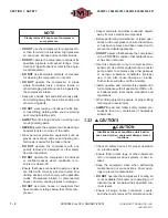
WARNING
Do not operate machine without hydraulic sys-
tem completely assembled.
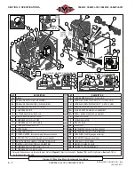
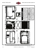
Refer to
Figure 3-1
or
Figure 3-2
.
Flow controller is optional to reduce
fl
ow if neces-
sary. Consult IMT
®
.
HYDRAULIC LINES
The following is a minimum requirement and NO
quick disconnects may be used. Lines are to be
kept as straight and short as possible.
• Pressure port = Standard, #12, 3/4” hose (lo-
cated at manifold block)
• Load sense = #4 JIC = 1/4” hose (Used for
closed center system only)
• Pressure relief/case drain = #6 JIC = 3/8” hose
• Hydraulic suction = Standard, #16, 1” hose
3.4.3 STANDARDS GUIDELINES
• Hydraulic pressure relief factory set at 3200 psi.
3.5 INSTALLATION
3.5.1 MACHINE LOCATION
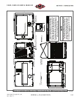
It is vital to locate the machine so that there is
no restriction of cooling air through the enclosure
(Refer to
Figure 3-3
). Cooling air enters the en-
closure at the rear (cooler) package end of the
machine, passes through the cooler and exits
through vents in the upper sides and the front.
3.5.2 CLEARANCES
Refer to
Figure 3-3
. Ensure that adequate sur-
rounding clearance space exists around the ma-
chine to allow for adequate cooling ventilation
through the canopy shroud, unobstructed service
access, and a clear view of the control panel. An
approximate recommendation of ten (10) inches
clearance, minimum, is needed for proper cool-
ing circulation, plus any additional service access
room included where needed.
3.5.3 MACHINE STABILIZATION AND
GROUNDING
Refer to
Figure 3-5
. Machine should be mounted
to vehicle using a minimum of four (4) isolators.
Isolators absorb vibration. Isolators are included
with the machine.
NOTE
Isolator replacements are available from IMT
®
;
order bolt down isolator no. 71417230 (unit
uses four [x 4] isolators).
WARNING
GROUNDING STRAP: If the machine and/or
instrument panel respectively are isolated
from contacting the chassis (paint
fi
berglass
body, rubber mounts, etc.), then the machine
must be grounded to the truck chassis with a
minimum two (2) ga wire.
If the machine is bonded by traditional hard
mounting (metal to metal contact with chas-
sis), then the grounding strap is not required.
3.5.4 SERVICE CONNECTIONS
Refer to
Figure 3-1
or
Figure 3-2
. Service con-
nections are conveniently grouped at the lower
rear section of the unit in the base frame.
3.5.5 ELECTRICAL CONNECTIONS
Refer to
Figure 3-1
or
Figure 3-2
. Connect the
electrical supply connector, located at the con-
Summary of Contents for CAS40PL
Page 2: ...BLANK PAGE...
Page 81: ...BLANK PAGE...

