background image


Parts 31 


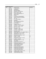
23000080 PARTS LIST


ITEM PART 

DESCRIPTION 

QUANTITY 

1. 70073051 

COMPRESSOR 

2. 52719724 

RESERVOIR 

3. 52720047 

BASE 

WELDMENT 

52724369 

BRACKET (WAS 52070749) 

5. 

70058486 

BELT-POWER V 2B80 

6. 70056043 

PULLY-BROWNING 

2BK110H 

7. 52705590 

BELT 

GUARD 

8. 60104650 

BRACE 

9. 73051614 

HYD 

MOTOR-M20A897BEEF10 

10. 

73540449 

RELIEF VALVE (WAS 73054995) 

11. 73014671 FILL 

CAP 

12. 

73141276 

FILL NECK SCREEN 

13. 60106708 BUSHING 

14. 

52702304 

BOLT-CMPRSR HOLD DOWN 

15. 

52706302 

TIGHTENER BOLT 8" 

16. 73052133 OIL 

COOLER 

17. 60104673 SLEEVE 

.39X1X1.19 

19. 

72060094 

CAP SCR 1/2-13X1-3/4 HHGR5 

20. 

72060091 

CAP SCR 1/2-13X1 HHGR5 

21. 

72062080 

NUT 1/2-13 LOCK 

10 

22. 

72063053 

WASHER 1/2 LOCK 

24. 

72060008 

CAP SCR 1/4-20X2 HHGR5 

25. 

72060004 

CAP SCR 1/4-20X1 HHGR5 

26. 

72063001 

WASHER 1/4 WRT 

13 

28. 

72661642 

HOSE CLAMP 1-3/4 T-BOLT (WAS 72066516) 

29. 

72532833 

BEAD NIPPLE 1MPT 1-1/4HOSE 

30. 

72531550 

BARB NIPPLE 1-1/4MPT 1-1/4 

31. 

73052091 

RETURN FILTER 10MIL 1-1/4FPT 

32. 

89393401 

HOSE 1-1/4 100R4 

40" 

33. 

89393401 

HOSE 1-1/4 100R4 

60" 

34. 

72053211 

PIPE NIPPLE 1-1/4NPT X CLOSE 

35. 

72053327 

ELBOW 1-1/4NPT 90° 

36. 

72053141 

PIPE NIPPLE 3/4NPT X CLOSE 

37. 72053604 TEE 

3/4NPT 

38. 

73053285 

STREET ELBOW 3/4NPT 90° 

39. 72053436 REDUCER 

COUPLING 1.0-3/4NPT 

40. 

72053747 

ADAPTER #12MSTR 3/4FPT 

41. 

72053676 

ADAPTER 3/4MPT #12MJIC 

42. 

51705296 

HOSE ASM 3/4X20 FF 

43. 

72532367 

ADAPTER #16MSTR #12MJIC 

44. 

73054435 

PRESSURE GAUGE 5000PSI 

45. 

72531131 

STREET ELBOW 1/4NPT 90° 

46. 

72053747 

ADAPTER #12MSTR 3/4FPT 

47. 

72053713 

ELBOW 3/4MPT 1/4FPT 90° SWVL 

48. 

72053558 

ADAPTER 3/4MPT 3/4MPT 

49. 

72053750 

ADAPTER #16MSTR 3/4FPT 

Summary of Contents for CAS440HT

Page 1: ...te http www imt com Copyright 2012 Iowa Mold Tooling Co Inc All rights reserved No part of this publication may be reproduced stored in a retrieval system or transmitted in any form or by any means el...

Page 2: ......

Page 3: ...veline and Pump Installation 13 Topdeck Compressor Installation 15 Oil Cooler optional 17 Operation 19 Operation 19 Shutdown 20 Maintenance Repair 21 Maintenance Schedule 22 Compressor Hydraulic Oil 2...

Page 4: ...CHANGE DURATION ECN 10523 CHANGED 28 72066516 TO 72661642 20071127 MAINT SCHEDULE ECN 10612 CHANGED NOTE IN MAINTENANCE SCHEDULE TO 6 MONTHS 20090409 23000080 ADDED CALLOUT FOR ITEM 9 MOTOR ADDED SPEC...

Page 5: ...legible The equipment owner and or designated employee is responsible for informing all operators maintenance personnel and others involved in equipment operation about the safe operation and mainten...

Page 6: ...manual three means are used to draw the attention of personnel They are NOTEs CAUTIONs and WARNINGs and are defined as follows NOTE A NOTE is used to either convey additional information or to provid...

Page 7: ...il under pressure can cause severe injury or death Shut down let cool and relieve pressure in compressor before servicing All electrical components and cable wiring must be installed and grounded in a...

Page 8: ...Do not attempt to service any part while the machine is operating WARNING AVOID PERSONAL INJURY OR PROPERTY DAMAGE Check the compressor sump oil level only when the compressor is not operating and the...

Page 9: ...g parts Keep combustibles out of and away from the compressor and any associated enclosures The owner lessor or operator of the compressor are hereby notified and forewarned that any failure to observ...

Page 10: ...ing Critical or Normal Wear items during the first year of operations and you need to contact the distributor or manufacturer for availability PART NO DESCRIPTION QTY CODE COMPRESSOR ASSEMBLY COMPONEN...

Page 11: ...N 10 microns PRESSURE SWITCH 175 psi off 150 psi on 12 psi off 10 psi on COMPRESSOR PULLEY RPM 980 rpm 900 1000 NORMAL OPERATING PRESSURE 1850 psi 130 bar MAXIMUM PRESSURE 2400 psi 165 bar GPM 16 gpm...

Page 12: ......

Page 13: ...irection in which the PTO must turn 5 PTO torque required If possible use a hydraulic pump directly mounted to the PTO This will eliminate an auxiliary driveshaft and it is easier to install as it eli...

Page 14: ...Remove the PTO from its shipping container Inspect for foreign objects which may have lodged in the PTO cavity 8 Mount the PTO per manufacturer s instructions 9 Check backlash per manufacturer s instr...

Page 15: ...et to the adjustable bracket 3 Bolt the adjustable bracket to the frame at a point that will not exceed 48 122cm from the PTO and will not cause a joint angle greater than 8 4 Check the pump rotation...

Page 16: ...hands hair clothes away with engine on WARNING AVOID DEATH OR SERIOUS INJURY The driveline installer must inspect the final position of the driveline to determine whether an operator or other personne...

Page 17: ...ce a 1 3 4 diameter grommet into the hole to help prevent hose wear 4 Route the hose through the hole and connect it to the pump and control valve using the fittings provided 5 Drill a 2 1 4 hole in t...

Page 18: ...e PTO and start the truck engine Depress the clutch and engage the PTO Release the clutch slowly It may be necessary to allow the truck to idle until warmed up enough to pull at idle RPM Push the comp...

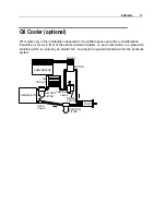
Page 19: ...s Install the oil cooler in front of the carrier vehicle s radiator or as an alternative in a protective structure which is cooled by an electric fan See figure for general location within the hydraul...

Page 20: ......

Page 21: ...disengaged control valve is open pull the compressor switch out and the receiver drain cock is open 2 Start the truck engine and allow it to idle until it reaches the proper operating temperature refe...

Page 22: ...or system as follows 1 Allow the compressor to build to maximum pressure and the truck engine will automatically idle down 2 Place the compressor control valve in the open off position 3 Depress the c...

Page 23: ...AINTENANCE CHART lists serviceable items on this compressor package The items are listed according to their frequency of maintenance followed by those items which need only As Required maintenance The...

Page 24: ...lt tension check Drain condensation manual RECEIVER Safety valves operate Oil reservoir level check Filter check and change Leaks check repair Safety door switch check PTO cable check Speed control re...

Page 25: ...inimum Viscosity SSU 100 F 140 190 100 130 150 200 200 315 Minimum Viscosity SSU 210 F 40 41 43 47 Minimum Viscosity Index 139 90 90 90 Additives including anti foam inhibitors antioxidant inhibitors...

Page 26: ...d can significantly shorten the efficient service life of the unit Periodically draw off a sample of the oil and check the oil for breakdown To check oil quality 1 Place the oil in a clean glass 2 Sme...

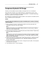
Page 27: ...suction hose to the pump drain and reassemble Change the suction filter cartridge NOTE DISPOSE OF WASTE OIL IN A RESPONSIBLE MANNER FOLLOWING ANY FEDERAL STATE OR LOCAL REGULATIONS 2 Remove the reser...

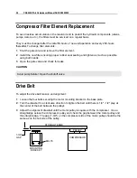
Page 28: ...Open the gate valve and check for leaks CAUTION Avoid pump failure Open the shutoff valve Drive Belt To adjust the drive belt tension and alignment 1 Loosen the four bolts securing the motor mounting...

Page 29: ...ressure before proceeding with a repair Carefully loosen a fitting and allow the pressure to bleed off 2 NEVER allow foreign matter dirt water metal particles etc to enter the system through the open...

Page 30: ...or If this does correct the problem replace the valve Motor does not turn when hydraulic valve is closed Oil does not reach 2300 2500 psi 1 Compressor is locked up Disconnect the drive system and try...

Page 31: ...29 S E C T I O N 6 Parts...

Page 32: ...69 7 26 25 17 26 33 32 28 33 16 28 29 39 36 38 51 73 32 28 30 31 34 35 34 60 72 50 26 FRONT OF TRUCK 26 14 51 50 20 22 26 50 21 21 19 51 15 37 41 42 36 11 12 2 20 22 20 22 3 21 40 TO PUMP 43 44 45 19...

Page 33: ...R 1 4 20X2 HHGR5 2 25 72060004 CAP SCR 1 4 20X1 HHGR5 3 26 72063001 WASHER 1 4 WRT 13 28 72661642 HOSE CLAMP 1 3 4 T BOLT WAS 72066516 4 29 72532833 BEAD NIPPLE 1MPT 1 1 4HOSE 2 30 72531550 BARB NIPPL...

Page 34: ...72053533 STREET ELBOW 1 4NPT 45 1 57 70048069 MOISTURE REGULATOR 1 58 72532552 HOSE FITTING 1 4 1 4 TYPE O 1 59 72053013 PIPE NIPPLE 1 4NPT X CLOSE 1 60 72532960 PIPE NIPPLE 1 1 4X11 1 61 72053245 PIP...

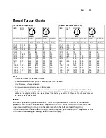
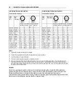
Page 35: ...1360 1 3 8 12 1 375 1675 1255 2710 2035 1 3 8 6 1 375 1470 1100 2380 1780 1 1 2 12 1 5 2195 1645 3560 2670 1 1 2 6 1 5 1950 1460 3160 2370 NOTES 1 Tightening torques provided are midrange 2 Consult b...

Page 36: ...375 232 174 375 281 1 3 8 6 1 375 203 152 329 246 1 1 2 12 1 5 304 228 492 369 1 1 2 6 1 5 270 210 438 328 NOTES 1 Tightening torques provided are midrange 2 Consult bolt manufacturer s particular spe...

Reviews: