1
M29-0002-00A REV 1.0
Quick Start Guide for IMTDragonFly
Objective:
“This guide describes the steps to install and operate an IMTDragonFly Transmitter”
Connections and Power
•
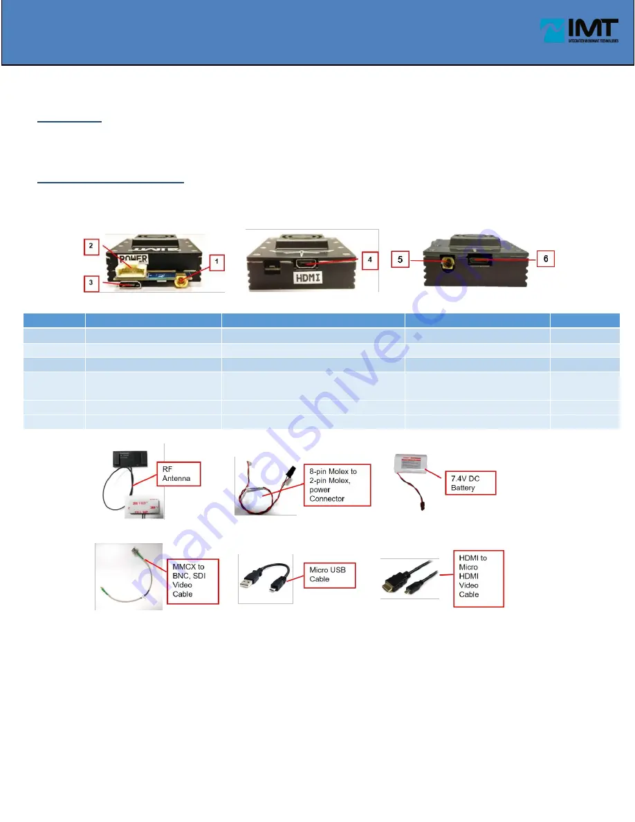
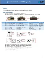
There are three major connections to be made on the DragonFly:
•
The white Molex 8 pin cable is the power control cable. The black cylindrical wire next to it is the RF output cable.
Number
From
To
Function
Unit Type
1 Dragonfly MMCX Female
Antenna MMCX Male
RF Antenna
SDI/HDMI
2 DragonFly 8-pin Molex
Bare leads or 2-pin Molex connector
Powering the Dragonfly
SDI/HDMI
3 DragonFly Micro USB 2.0
Computer - USB A Male
Programming the Dragonfly
SDI/HDMI
4 Dragonfly HDMI
Camera HDMI
–
Micro HDMI
HDMI Video input(only on
HDMI units)
HDMI
5 Dragonfly MMCX
Camera SDI-BNC
SDI Video Input
SDI
6 Dragonfly 6 pin connector
Camera RS-485
Camera Control Cable
SDI
•
Use only lithium ion batteries at 7.4VDC – 14VDC input to the power processor board.
•
You may use 7.4VDC balanced lithium-ion batteries in parallel for a longer run time.
•
Connecting the battery will automatically boot-up the transmitter.
•
Once the DF is powered, a little green LED light comes up next to the power connector
•
The fan also comes up when the DragonFly is powered ON
•
Upon boot-up the DragonFly will be on the last state it was turned off on.
•
Control is via Wi-Fi and Webpage


