background image

VST

X

 User Manual


Revision 

2.

3


46


Summary of Contents for VSTx

Page 1: ...VSTX HD SD COFDM Transmitter User Manual IMT PUBLICATION M22 0002 00A REV 2 3...

Page 2: ...ary 10 2012 2 2 Jason Wang Added FCC IC Label requirements January 25 2012 2 3 Jason Wang Added RP SMA Antenna Port for 25VST IMT VSTX Users Manual IMT Publication M22 0002 00A IMT LLC 200 Internation...

Page 3: ...rvicing Read and perform all instructions carefully Failure to follow suggested instructions and guidelines may void all warranties PRUDENCE RISQUE DE CHOC LECTRIQUE NE SUPPRIMEZ PAS LES COUVERTURES N...

Page 4: ...nnuler l autorisation de l utilisateur pour l exploitation de ce dispositif Ce dispositif n cessite l installation professionnelle Pour l op ration au sein de la gamme de fr quences de 2400 2483 5 MHz...

Page 5: ...this device Le pr sent metteur radio identifier le dispositif par son num ro de certification ou son num ro de mod le s il fait partie du mat riel de cat gorie I a t approuv par Industrie Canada pour...

Page 6: ...el can use wording such as the following Contains Transmitter Module FCC ID I4U 25VST IC 9479A 25VST or Contains FCC ID I4U 25VST IC 9479A 25VST Any similar wording that expresses the same meaning may...

Page 7: ...Control and Firmware 21 2 1 1 Remote Control via Serial Interface 21 2 1 2 Firmware updates 21 3 Specifications 24 3 1 Frequency Bands 24 3 2 Modulation Modes 24 3 3 MPEG Encoder 25 3 4 System 25 3 5...

Page 8: ...ransmit Audio and Video Signals 43 5 4 1 Select User Level Settings 43 5 4 2 Put the unit in Transmit Mode 43 5 4 3 Select Power Level 43 5 4 4 Verify Operation 43 5 5 Using the VSTX To Transmit User...

Page 9: ...27 4 4 1 Power and Control Connector Housing 27 4 4 2 Video Input Connector Housing 29 4 4 3 Audio Input Connector Housing 29 4 5 Connect External Signals Ribbon Housing 29 4 6 Antenna Installation 3...

Page 10: ...er Level 37 5 4 4 Verify Operation 37 5 5 Using the STx To Transmit User Data 37 5 6 Using alternate custom controllers 38 5 6 1 Serial Interface Rate Parity and Stop Bit Specifications 38 5 6 2 Comma...

Page 11: ...__________ 32 Figure 4 7 VSTx Connector Housing Power Control Detail __________________________________________ 34 Figure 4 8 VSTx Connector Housing Audio Detail ______________________________________...

Page 12: ...VSTX User Manual Revision 2 3 12...

Page 13: ...VSTX User Manual Revision 2 3 13 Chapter One 1 Introduction...

Page 14: ...terface panel and a ribbon cable version which has no external connectors or controls Throughout this manual the product is referred to as the VSTX the VSTX transmitter or simply the transmitter 1 1 M...

Page 15: ...VSTX User Manual Revision 2 3 15 Chapter Two 2 Description...

Page 16: ...a into ISO digital video transport streams and optionally encrypts the data The transmitter uses COFDM modulation and transmits at microwave frequencies in the bands supported by the unit Though the u...

Page 17: ...STX uses a compact flexible ribbon cable to connect to other equipment 2 1 1 VSTX Application Diagram Figure 2 1 shows a typical VSTX transmitter application The External Equipment Interface connects...

Page 18: ...s a block diagram of the VSTX internal circuitry Major blocks in the VSTX include NTSC Composite Video Input Interface Stereo Audio Input Interface MPEG4 Video Compression Circuit Data Encryption Circ...

Page 19: ...Data Encryption Microwave Transmitter Microprocessor and Flash Memory Power Audio Input Circuit Video Input Circuit User Data Serial Port Programmable Serial Port USB Interface Circuit Ribbon only UI...

Page 20: ...interface on the ribbon connectorin the Power Control connector 2 1 5 MPEG4 Encoder The VSTX compresses the input video signal before modulation and transmission to reduce bandwidth The VSTX contains...

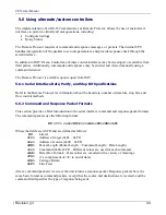
Page 21: ...ctor pin assignments and antenna port 2 1 Remote Control and Firmware 2 1 1 Remote Control via Serial Interface An RS 232 command set is implemented to allow remote control of all configuration option...

Page 22: ...VSTX User Manual Revision 2 3 22...

Page 23: ...VSTX User Manual Revision 2 3 23 Chapter Three 3 Specifications...

Page 24: ...3 8 Other bands may be available Contact IMT Tuning step size 1MHz step size Frequency stability 10ppm Transmit Modes Standby No RF output Normal Instantly on frequency transmission 3 2 Modulation Mod...

Page 25: ...external bias Tone 10dBfs 8dBm Level Adjustable 10 to 26dBfs 3 4 System Video Present Remote Standby or Test Generator Test Generator Dynamic SMPTE CB NTSC 100 CB PAL 16 Character ID Matches SDT Servi...

Page 26: ...ange Storage 40 to 80 C Humidity 0 to 95 RH non condensing Altitude Operating 0 to 20 000ft 6 000 m Maximum Altitude Storage 0 to 50 000ft 15 000 m Maximum 3 7 Physical Specifications Size Flex versio...

Page 27: ...VSTX User Manual Revision 2 3 27 Chapter Four 4 Installation...

Page 28: ...open the VSTX housing Failure to comply will result in voiding of the VSTX warranty ______________________________________________________________ 4 1 Overview The VSTX is used in compact systems tha...

Page 29: ...g The Connector style unit will have either a Button LED faceplate or a Rotary Key or a Blank faceplate 4 2 1 Connector Housing C E F F F F D A B A Video Input D Power and RS 232 Interface B Audio 1 A...

Page 30: ...VSTX User Manual Revision 2 3 30 Figure 4 3 VSTX Button LED faceplate Figure 4 4 VSTX Rotary Key faceplate...

Page 31: ...vision 2 3 31 4 2 2 Ribbon Housing C D A A A A B E A Screw Holes for Mounting D Ribbon Cable B VSTX Top Surface E Antenna Port C Ribbon Cable Connector Arrow points to Pin 1 26 pins total Figure 4 5 V...

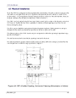
Page 32: ...2 56 screws Tighten the four screws gradually in rotation without applying excess force on one before starting the others The STx requires installation using proper thermal dissipation methods During...

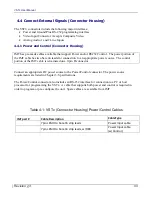
Page 33: ...he control portion of the IMT cable is terminated on a 9 pin D connector Connect an appropriate DC power source to the Power Control connector The power source requirements are listed in Chapter 3 Spe...

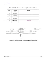
Page 34: ...ision 2 3 34 Table 4 2 VSTx Connector Housing Power Control Pinout Pin Function Notes 1 12VDC 2 RS232 RX 3 USB DM 4 USB DP 5 RS232 TX 6 USB POWER Not Active 7 GROUND Figure 4 7 VSTx Connector Housing...

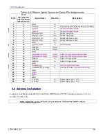
Page 35: ...grounding the VSTX ribbon cable should be connected to an interface that terminates all the signals Do not attempt to split the cable or use multiple connectors on the end of the ribbon To terminate...

Page 36: ...B Interface 11 11 USB_DP In Out 12 12 USB_DM In Out 13 13 GND 14 14 n aAUDIO1 W Bias In Out Audio 1 single ended with Mic Bias 15 15 n aAUDIO2 W Bias In Out Audio 2 single ended with Mic Bias 16 16 AU...

Page 37: ...VSTX User Manual Revision 2 3 37 Chapter Five 5 Operation...

Page 38: ...udes an appropriate heat sink Refer to the thermal specifications in Chapter 3 Specifications The VSTX must be mounted using appropriate methods to ensure that the bottom surface of the unit is kept w...

Page 39: ...LED s will indicate which preset is currently selected The unit will begin to implement the selected preset five seconds after the last button push The appropriate LED will blink Red as the changes ar...

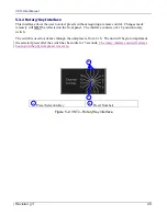
Page 40: ...e front panel The interface consists of a 16 position rotary switch The switch is used to advance through the unit presets from 1 16 The unit will begin to implement the selected preset after the swit...

Page 41: ...rol or indications Changes made remotely will NOT be reflected on the unit The interface consists of a 26 pin ribbon cable See Section 4 Installation for pin assignments C D C Ribbon Cable Connector A...

Page 42: ...download mode 5 3 3 5USB_DP USB_DM USB signal 5 3 3 6Composite Video S Video The unit activates these inputs based on the video input selection made by the user either Composite Video or S Video Comp...

Page 43: ...n Depending on unit type Standby mode status may be indicated by a front panel LED 5 4 3 Select Power Level Use the remote control to select the power level desired HI LOW In HI mode the unit will out...

Page 44: ...cifications Refer to the Remote Protocol for information about the baud rate number of data bits stop bits and flow control methods 5 6 2 Command and Response Packet Formats This section provides a br...

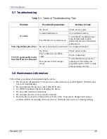
Page 45: ...bbon cable Check connections Host processor GUI settings issues Verify that the host processor running a GUI interface for programming the VSTX is setup and operating correctly 5 8 Maintenance Informa...

Page 46: ...VSTX User Manual Revision 2 3 46...

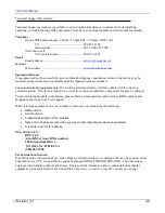
Page 47: ...normal conditions of operation or attempts to repair by other than authorized service personnel shall be excluded from this warranty IMT shall in no event be responsible for incidental injury or prope...

Page 48: ...If no fault is found or no corrective action is authorized a diagnostic fee may be charged Prior to returning products to the factory please obtain a return material authorization RMA number and ship...

Page 49: ...VSTX User Manual Revision 2 3 49...

Page 50: ...VSTX User Manual Revision 2 3 50 IMT LLC 200 International Drive Mt Olive NJ 07828 USA T 1 908 852 3700 F 1 908 813 0399 www imt solutions com...

Reviews: