SD Logger
4
instruction manual[X519009-3]
12/28
<2020/03/03>
(
3
rd
edition
)
1-3
)
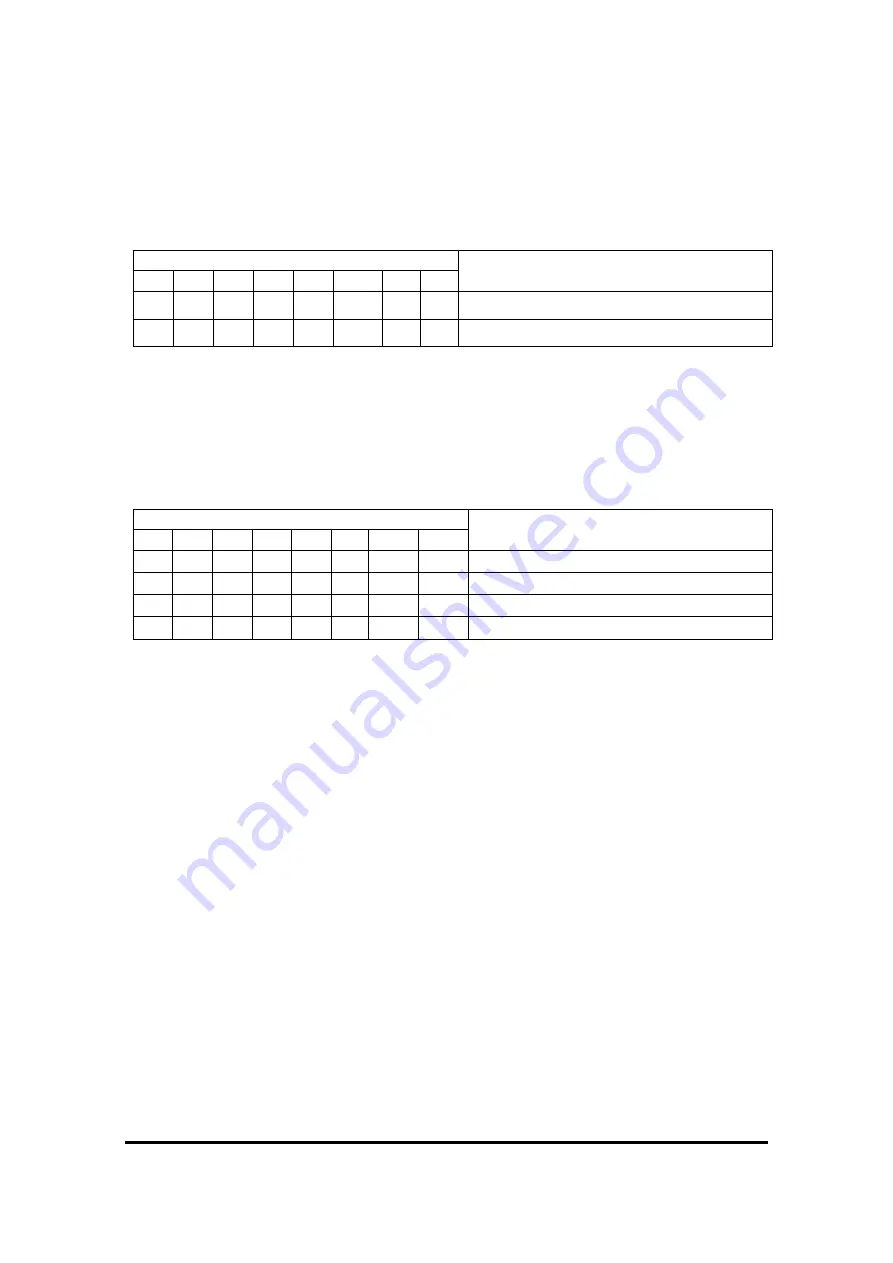
Data bit / stop bit
Data bits and stop bits are set by operating DIP switch [6].
The correspondence between switch ON / OFF and data bit / stop bit is shown
in the table below.
No.
Data bit / stop bit
[1] [2] [3] [4] [5]
[6]
[7] [8]
-
-
-
-
-
OFF
-
-
8 data bits and 1 stop bit
-
-
-
-
-
ON
-
-
Follow configuration settings.
※
In configuration mode and update mode, even if data bit 7 is set
in configuration settings, data bit 8 operates.
1-4
)
Mode
The mode is set by operating DIP switches [7] and [8].
The correspondence between the switch ON and OFF and the mode is as shown
in the table below.
No.
Mode
[1] [2] [3] [4] [5] [6]
[7]
[8]
-
-
-
-
-
-
OFF OFF Normal
-
-
-
-
-
-
ON OFF Configuration mode
-
-
-
-
-
-
OFF ON Status display (maintenance) mode
-
-
-
-
-
-
ON
ON Update (programming) mode
※
The maintenance mode is for checking maintenance information and
for maintenance. Normally, use it in non-maintenance mode.
※
If a card is installed, it will not be in configuration mode or update mode.
Remove the card to use in configuration mode or update mode.
※
Do not use a mechanical pencil for dip switch operation.
Mixing the core powder into the inside may cause malfunction.


