background image

NCSTS9

3

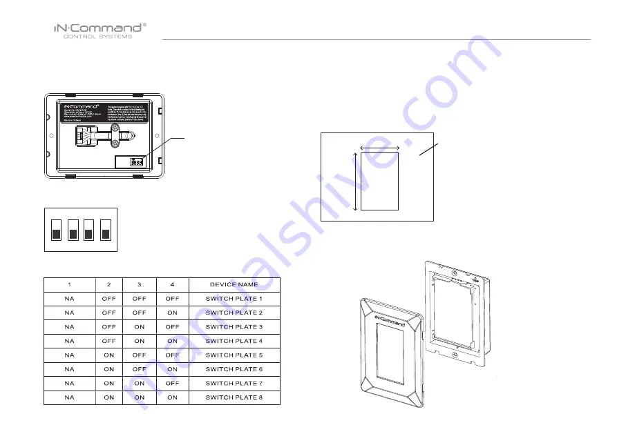
• DIP SWITCHES

The DIP switches mapping with device name.

 1    2    3    4

ON

Up to 8 Touch Switches can be added to a single floor plan.

To add multiple Touch Switches, adjust the DIP switch on 


the back accordingly.

1    2    3    4

Lifting PET film allows 

access to DIP switch 

adjustment

•  Mounting the Touch Switch Panel


• Cut/Drill hole, allowing space below for future programming and

      behind for ventilation

• Route wires through the hole and connect

• Check and ensure correct operation 

• Mount the unit using two #6 PFH(0.14"x0.50") screw

Wall for reference

Hole sizes 2.92"x3.86"  

Recommended Cutout

•  Installation

1.  Remove the Front cover from the front of the Touch Switch. 

2.92"

3.86"

Summary of Contents for NCSTS9

Page 1: ... Installation and Operation Manual NCSTS9 RV Touch Switch ...

Page 2: ......

Page 3: ... to installation Selecting the Mounting Location Select a mounting location taking care to avoid the following Places exposed to heat radiating appliances such as electric heaters Adjacent to other equipment that radiates heat Poorly ventilated or dusty places Moist or humid locations INTRODUCTION Key Features 3 2 back lit LCD touchscreen Designed for NCSP3 NCSP35 iN Command systems Total 9 assign...

Page 4: ...T film allows access to DIP switch adjustment Mounting the Touch Switch Panel Cut Drill hole allowing space below for future programming and behind for ventilation Route wires through the hole and connect Check and ensure correct operation Mount the unit using two 6 PFH 0 14 x0 50 screw Wall for reference Hole sizes 2 92 x3 86 Recommended Cutout Installation 1 Remove the Front cover from the front...

Page 5: ...RV C cables to the NCSTS9 4 Reattach the Front cover by placing it over the upper four clips and push it into place until it clicks Push until click 3 Use screws to attach the NCSTS9 to the wall Power RV C Connectors BLACK GND RED ...

Page 6: ...e to update the Floor Plan 4 Press load next to the floor plan created for the Display Commander and NCSTS9 1 Select Settings 2 Select Software Loading the Floor Plan The floor plan for the NCSTS9 gets loaded through the NCSP3 35 Display Commander ...

Page 7: ... located or operating in conjunction with any other antenna or transmitter No change to the antenna or the device is permitted Any change to the antenna or the device could result in the device exceeding the RF exposure requirements and void user s authority to operate the device This equipment generates uses and can radiate radio frequency energy and if not installed and used in accordance with t...

Page 8: ...MA 1709002 1R Features and specifications subject to change without notice For further technical support call 1 877 305 0445 ...

Reviews: