background image

800-446-7488

21

www.in-situ.com

Screen Element

Definition

The

Alarm

icon provides additional instrument status

information.

Green—No alarms or warnings

Yellow—One or more warnings

Red—One or more alarms

Move the cursor over the alarm icon to view a description.
Click the

Device Setup

tab for detailed information on the

alarm or warning.

(Not applicable for Aqua TROLL 400 and RDO PRO-X.)

System Time

is displayed on the left.

Device Time

is displayed on

the right. Clocks are updated once every two seconds. When the

Device Time

is displayed in red, it differs from the current

System

Time

, and should be synchronized.

The

Time Sync

button is used to write the current PC time to the

instrument. If you need to set the instrument clock to a time other
than the system (PC) time, use the

Set Clock

button on the

Device

Setup

tab.

Meter View

shows the last known parameter values, displayed with

current units and time stamp. Readings are sized to occupy the
entire screen. This is the default display in the

Home

tab. If the type

is black, the readings are updating in real time.

List View

is a running list of the most recent records. New readings

are continuously added to the top of the list and old readings scroll
off the bottom.

Graph View

shows a real-time trend graph of the selected

parameters.

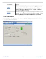
The

Snapshot

button allows you to take a snapshot of the data that

currently appears on screen and save it to a file. Non-logging
instruments can save data as CSV files but not as WSL data files.

The

Stop

button allows you to continuously record live data and

save it to a file. Non-logging instruments can save data as CSV files,
but not as WSL data files.

The

Play

button allows you to start and stop data polling.

Summary of Contents for Aqua Troll 400

Page 1: ... logo Baro Merge BaroTROLL HERMIT HydroVu iSitu Pocket Situ RDO RuggedCable RuggedReader SmarTROLL TROLL VuSitu and Win Situ are trademarks or registered trademarks of In Situ Inc 2012 2015 All rights reserved This product may be covered by patents identified at www in situ com patents 0088302 2018 05 15 ...

Page 2: ...ademarks of In Situ Inc Microsoft and Windows are registered trademarks of Microsoft Corporation Pentium is a registered trademark of Intel Tefzel and Delrin are registered trademarks of E I DuPont de Nemours and Company Viton is a registered trademark of DuPont Dow Elastomers Kellems is a registered trademark of Hubbell Inc Alconox is a registered trademark of Alconox Company Lime A Way is a regi...

Page 3: ...nts 10 Probe Dimensions with Restrictor On 11 Probe Dimensions with Restrictor Off 11 Sensors 12 Cable 12 Win Situ 5 Software 12 7 Probe Setup 13 Installing the Sensors 14 8 Communication Settings and Calibration 15 Connect the Instrument to the Computer 15 Connect the Instrument to Win Situ 5 Software 15 Data Tab 16 Set Communication Outputs 17 Modbus Setup 18 SDI 12 Setup 19 View and Record Data...

Page 4: ...Sensor Health Table 36 Sensor Health Table 37 10 Care and Maintenance 38 Maintenance Schedule 38 User Serviceable Parts 38 O rings 38 RDO Sensor Cap Replacement 38 pH ORP Sensor Replacement 38 Instrument Storage 38 Cleaning the pH ORP Sensor 39 Remove Crystalline Deposits 39 Remove Oily or Greasy Residue 39 Remove Protein Like Material or Slimy Film 39 Cleaning the RDO Sensor 39 Clean the Sensor C...

Page 5: ...munication Settings and Sensor Calibration Chapter 9 Controller Requirements and Connections Chapter 10 Care and Maintenance Chapter 11 Declaration of Conformity Modbus registers and SDI 12 programming information can be found in the Modbus and SDI 12 Reference Guide Serial Number Location The serial number is located on the large label on the instrument body The serial number is programmed into t...

Page 6: ...ors removed and cable detached Reading rate 1 reading every 5 seconds no internal logging Power Required 8 36 VDC no internal battery Measurement current 16 mA 24 VDC Sleep current 40 µA 24 VDC Interface In Situ Con TROLL PRO System In Situ TROLL Link Telemetry 101 or 201 System SCADA PLC and third party data loggers samplers controllers and telemetry systems Cable Customizable non vented absolute...

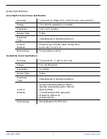
Page 7: ...its of Measure Pressure psi kPa bar mbar mmHg inHg Level mm cm m in ft Methodology Piezoresistive ceramic Conductivity Sensor Specifications Accuracy Typical 0 5 1 μS cm 1 max Range 5 to 100 000 μS cm Resolution 0 1 μS cm Sensor Type Fixed Response Time Instantaneous in thermal equilibrium Units of Measure Actual conductivity μS cm mS cm Specific conductivity μS cm mS cm Salinity PSU Total dissolv...

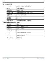
Page 8: ... 01 mg L Sensor Type Fixed with replaceable RDO Sensor Cap life 1 year typical Response Time T90 45 sec T95 60 sec Units of Measure mg L saturation ppm Methodology EPA approved In Situ Methods 1002 8 2009 1003 8 2009 1004 8 2009 ORP Sensor Specifications Accuracy 5 0 mV Range 1400 mV Resolution 0 1 mV Sensor Type Replaceable pH ORP combo sensor Response Time 15 sec Units of Measure mV Methodology ...

Page 9: ...placeable pH ORP combo sensor Response Time 15 sec pH 7 to pH 4 Units of Measure pH units Methodology Std Methods 4500 H EPA 150 2 Temperature Sensor Specifications Probe Accuracy 0 1 C Range 5 to 50 C 23 to 122 F Resolution 0 01 C or better Sensor Type Fixed Response Time 30 sec temperature sensor only Units of Measure Celsius Fahrenheit Methodology EPA 170 1 ...

Page 10: ...rfaces for use with an external controller System Components The system includes the following components l Integrated sensors RDO conductivity pressure and temperature l Plug in pH ORP sensor l Classic Cap Fast Cap or RDO X Sensor Cap The Aqua TROLL 400 ships with the RDO X Cap l Stainless steel restrictor l Calibration and storage cup l and cable Accessories purchased separately l Replacement RD...

Page 11: ...sions with Restrictor On Total length with connector 296 49 mm 11 7 in Total length without connector 269 11 mm 10 6 in Restrictor length 118 24 mm 4 7 in Diameter 47 mm 1 85 in Probe Dimensions with Restrictor Off Sensor length 81 09 mm 3 2 in ...

Page 12: ...t lock connection to the instrument and a stripped and tinned termination that must be wired to a controller Cable length is customizable Maximum length is 1 219 m 4 000 ft for Modbus output and 60 9 m 200 ft for SDI 12 output Win Situ 5 Software The Win Situ 5 Software is used to calibrate the sensors and to configure the instrument settings to communicate with a process controller or data logger...

Page 13: ...and protective dust caps in place 1 Dust cap protector on the RDO Sensor Install the RDO Cap before deploying the instrument 2 pH ORP storage plug Remove the storage plug and install the pH ORP sensor before deploying the instrument 3 Dust cap protector on the twist lock cable connector ...

Page 14: ...to position 5 Remove the orange plug from the pH ORP sensor port 6 Use the alignment marks to properly align the pH ORP sensor with the port connection and press firmly into place Push until the sensor is completely inserted into the port 7 Twist the restrictor back onto the probe Important Avoid touching the sensor lens and the sensing material on the top of the cap Important The RDO Sensor Cap a...

Page 15: ...e equipment and use proper laboratory technique when calibrating the sensors and operating the instrument Connect the Instrument to the Computer Using a direct connect TROLL Com Communication Device powered with an AC DC power supply you can connect the Aqua TROLL 400 to a computer running Win Situ 5 Software version 5 6 22 or later Connect the Instrument to Win Situ 5 Software Install Win Situ 5 ...

Page 16: ...nication with a connected instrument The connected plug indicates the instrument is communicating with the software Click to disconnect the software from the instrument The Home tab displays real time readings from the instrument When connection to the instrument is first established the software displays one reading of all available parameters in light gray You must click the Play button at the b...

Page 17: ...are supported by the instrument The Device Setup tab allows access to instrument information and settings such as instrument name serial number firmware version communication settings diagnostics and factory reset options Set Communication Outputs The Device Setup Tab allows you to access communication settings instrument information and status factory reset diagnostics and alarm setup The instrum...

Page 18: ...18 www in situ com Modbus Setup Click the Modbus setup button and assign instrument settings according to the requirements of your controller For instrument Modbus registers see the Modbus and SDI 12 Reference Guide ...

Page 19: ...rument address select the parameters you intend to log and select the order in which the parameters will appear in your SCADA system or datalogger file See the Help menu in Win Situ 5 Software for details To view SDI 12 programming information see the Modbus and SDI 12 Reference Guide ...

Page 20: ...tton Screen Element Definition The Sites button allows you to add edit or delete a site Not applicable for Aqua TROLL 400 and RDO PRO X These icons allow you to view the memory and battery usage for an instrument that includes internal logging Not applicable for Aqua TROLL 400 and RDO PRO X This icon allows you to view the logging status for an instrument that includes internal logging Not applica...

Page 21: ...n the system PC time use the Set Clock button on the Device Setup tab Meter View shows the last known parameter values displayed with current units and time stamp Readings are sized to occupy the entire screen This is the default display in the Home tab If the type is black the readings are updating in real time List View is a running list of the most recent records New readings are continuously a...

Page 22: ...ting units and setting sentinel values When you click on the sensor you want to calibrate or configure the Calibration button and the Sensor Setup buttons become active Calibration Frequency Recommendations In Situ sensors are factory calibrated across the entire range of each sensor and thus achieve a very high degree of accuracy and stability for extended periods of time without user calibration...

Page 23: ...or 3 point Offset 30mV at pH 7 ORP 4 6 weeks or as required by user protocol or site conditions 12 months Offset 30 mV RDO 12 months or as required by user protocol or site conditions 12 months 2 point Slope 0 7 to 1 3 2 point Offset 0 3 mg L Factory Calibration Factory calibration includes a thorough cleaning full functionality check and sensor adjustments to all applicable sensors over the entir...

Page 24: ...t allows you to select units for the parameter you selected Sentinel Offline Value This is a text field in which you can enter the value that you want to see in the data when a sensor is unable to communicate After you have entered a value click the Set button to save it Configure This button becomes active when you select a parameter that includes additional configuration options Click the Config...

Page 25: ... Oxygen Saturation 1 Place the calibration cap with the vent hole on the top of the calibration cup 1 Storage cap 2 Calibration cap with vent hole 2 Place the sponge wafer in the bottom of the calibration cup and saturate the sponge wafer with approximately 10 mL clean water 3 Gently dry the probe and sensing material with a paper towel Ensure that the probe and the sensing surface are free of wat...

Page 26: ...ment will be deployed 12 Click Next 13 Click OK to start the calibration 14 When the screen indicates that the calibration has reached stability click Accept to complete the calibration or click Cancel to return to the previous calibration Calibrate 0 Oxygen Saturation We recommend that you perform the 0 oxygen calibration only if you intend to measure dissolved oxygen at a concentration of less t...

Page 27: ...tes that the calibration has reached stability click Accept to complete the calibration or click Cancel to return to the previous calibration 8 You can save or print the calibration report 9 Click OK to complete the calibration 10 Once calibration is complete remove the instrument from the calibration cup and rinse both thoroughly with clean water ...

Page 28: ...ibration is recommended only if you must conform to a standard operating procedure or if the conductivity cell has undergone physical change e g deposits on conductivity cell walls that cannot be removed or physical damage to the conductivity cell walls 1 Fill the calibration cup to the fill line with approximately 130 mL of the desired calibration solution 2 Place the instrument in the solution t...

Page 29: ...o the previous calibration 12 You can save or print the calibration report 13 Click OK to complete the calibration 14 Once calibration is complete remove the instrument from the calibration cup and rinse both thoroughly with clean water Pressure Level The pressure sensor has been factory calibrated with NIST standards to a greater degree of accuracy than can be achieved in nearly any alternative s...

Page 30: ...RP calibration solution 2 Place the calibration cap on the instrument slightly above the restrictor and place the instrument in the solution taking care to not force the solution out the top of the calibration cup 3 In Win Situ 5 Software select the pH ORP sensor 4 Click the Calibrate button in the left corner of the screen ...

Page 31: ... time for the temperature to stabilize 10 Click OK to start the calibration 11 When the screen indicates that the calibration has reached stability click Accept to complete the calibration for that calibration point or click Cancel to return to the previous calibration 12 Follow the Wizard to continue through the remaining calibration points 13 You can save or print the calibration report 14 Click...

Page 32: ...s The shielded wire should be wired to a chassis ground or earth ground See Safety on page 5 Stripped and Tinned Cable Signal Color Ground Return Black External Power Red No Connection Brown RS485 Green RS485 Blue SDI 12 White Power Connections The Aqua TROLL 400 requires an external 8 to 36 VDC power source The red wire must be connected to the positive terminal of the power source The black wire...

Page 33: ...800 446 7488 33 www in situ com SDI 12 Wiring Diagram Cable length must not exceed 60 9 m 200 ft Signal Color Ground Return Black External Power 9 6 16 VDC Red SDI 12 White ...

Page 34: ...800 446 7488 34 www in situ com Modbus Master RS485 Wiring Diagram Cable length must not exceed 1 219 m 4 000 ft Signal Color Ground Return Black External Power 12 36 VDC Red RS485 Green RS485 Blue ...

Page 35: ...onverter Required Cable length between Master and Slave must not exceed 1 219 m 4 000 ft Cable length between Master and Converter must not exceed 6 m 20 ft Signal Color Ground Return Black External Power 12 36 VDC voltage limited by converter Red RS485 Green RS485 Blue ...

Page 36: ...r SDI 12 Modbus and SDI 12 cannot be used at the same time The protocol that is in use will block communication of the other See the Aqua TROLL 400 Modbus and SDI 12 Reference Guide for registers and programming information Prior to connecting the instrument to the controller you must configure communication settings using the Comm Kit Software and the Communication Device Device ID Device ID for ...

Page 37: ...ion ERR 3 Unknown Error Parameter measured with error sentinel value supplied WU 4 Sensor Warm up Sensor is warming up sentinel value supplied DIS 5 Sensor Warning Parameter measured but does not meet normal quality criteria The sensor has sustained moderate damage or the recommended lifespan has been reached CAL 6 Sensor Calibrating Sensor is calibrating calibration value supplied OL 7 Sensor Mis...

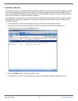
Page 38: ...llow the instructions included in the RDO Sensor Cap Replacement Kit Replacement caps are available from In Situ Inc or your authorized In Situ distributor pH ORP Sensor Replacement To replace the pH ORP sensor or to refill the reference junction follow the instructions in the pH ORP Sensor Instruction Sheet that is included with the replacement sensor Instrument Storage To store the probe for a w...

Page 39: ...ng in 5 HCI and 5 NaOH solutions Remove Oily or Greasy Residue 1 Clean the sensor with warm water and mild soap 2 Methanol or isopropyl alcohol may be used for short soaking periods up to 1 hour 3 Do not soak the sensor in strong solvents such as chlorinated solvents ethers or ketones including acetone Remove Protein Like Material or Slimy Film 1 Clean the sensor with warm water and mild soap 2 So...

Page 40: ...a soft swab and mild soap such as a dilute solution of dish detergent The probe is shipped with polyurethane foam swabs for this purpose You can also achieve good results using a gentle back and forth motion with a thin cotton pipe cleaner If debris is still present continue to Cleaning Procedure 2 If the sensor is clean skip to the last step Cleaning Procedure 2 Avoid damaging the plastic materia...

Page 41: ...800 446 7488 41 www in situ com Declaration of Conformity ...

Reviews: