background image

12

Level 

trOll

 Operator’s Manual

0052210  rev. 006

If an instrument 
returned for 
servicing 

shows evidence of 
having been deployed 
in a toxic or hazardous 
environment, Customer 
Service personnel will 
require written proof of 
decontamination before 
they can service the unit.

seCtion 1: introduCtion

guidelines For Cleaning returned equiPment

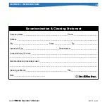
Please help us protect the health and safety of our employees by cleaning 
and decontaminating equipment that has been subjected to any potential 
biological or health hazards, and labeling such equipment. Unfortunately, 

we cannot service your equipment without such notification

. Please 

complete and sign the 

form

 on page 13 (or a similar statement certifying 

that the equipment has been cleaned and decontaminated) and send it 
along to us with each downhole instrument. 

•  We recommend a good cleaning solution, such as Alconox

®

, a 

glassware cleaning product available from In-Situ (Catalog No. 
0029810) and laboratory supply houses. 

•  Clean all cabling. Remove all foreign matter.

•  Clean cable connector(s) with a clean, dry cloth. Do not submerge. 

•  Clean the probe body—including the nose cone, cable head, and 

protective caps. Remove all foreign matter.

If an instrument is returned to our Service Center for  
repair or recalibration without a statement that it has been 
cleaned and decontaminated, or in the opinion of our Service 
Representatives presents a potential health or biological 
hazard, we reserve the right to withhold service until proper 
certification has been obtained.

TIP:

 Alconox

®

 is  

available from  
In-Situ Inc. 

(Catalog No. 29810).

Summary of Contents for BaroTroll

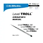
Page 1: ...Operator s Manual Level TROLL March 2010 Level TROLL 300 Level TROLL 500 Level TROLL 700 BaroTROLL ...

Page 2: ... including but not limited to its fitness for a particular application In Situ will not be liable for errors contained herein or for incidental or consequential damages in connection with the furnishing performance or use of this material In no event shall In Situ Inc be liable for any claim for direct incidental or consequential damages arising out of or in connection with the sale manufacture de...

Page 3: ...Serial Number 8 To Our Customers 9 What We Provide 10 Warranty Provisions 10 How to Contact Us 10 To Obtain Repair Service U S 10 Guidelines for Cleaning Returned Equipment 12 2 System Components 14 Body 14 Cable 14 Communication Cables 18 Power Components 19 Installation Accessories 20 Control Software 21 Product Specifications 22 ...

Page 4: ...e and Connect to the Level TROLL 32 The Home Screen 34 Customizing the Home Screen Display 35 Set the Clock 36 Add a New Site 37 Prepare to Log Data 40 Disconnect 42 5 About the Pressure Level Sensor 43 Pressure Depth and Level 44 Configuring Depth and Level 45 Pressure Sensor Calibration 48 Factory Recalibration 48 Field Recalibration 48 Barometric Compensation of Non Vented Pressure Level Data u...

Page 5: ...ing 60 Power Connections 65 Communications 65 Using Win Situ 65 For More Information 66 9 Care Maintenance 67 Operating Considerations 67 Factory Recalibration 67 Storage 68 General Maintenance 68 Cleaning Body and Front End 68 Twist Lock Connectors 69 Cable Vent Tube Vented Cable 69 Batteries 69 10 Troubleshooting 70 Troubleshooting Connections 70 Troubleshooting Data Logs 71 Troubleshooting Para...

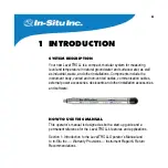
Page 6: ...ument body vented and non vented cables communication cables external power accessories desiccants and other installation accessories and software How to Use This Manual This operator s manual is designed as both a start up guide and a permanent reference for the Level TROLL s features and applications Section 1 Introduction to the Level TROLL Operator s Manual and to In Situ Inc Warranty Provisio...

Page 7: ...el Sensor The two basic types of pressure sensors Factory and field calibration Section 6 Field Installation Guidelines and Precautions for Long Term Deployment of the Level TROLL Section 7 The BaroTROLL Section 8 Connecting for use with SDI 12 Analog 4 20 mA and Modbus loggers and controllers Section 9 Care Maintenance Section 10 Troubleshooting Conventions Throughout this operator s manual you w...

Page 8: ...physical damage sustained during shipment Notify In Situ and file a claim with the carriers involved if there is any such damage do not attempt to operate the instrument Accessories may be shipped separately and should also be inspected for physical damage and the fulfillment of your order Serial Number The serial number is engraved on the body of the Level TROLL It is also programmed into the ins...

Page 9: ... imperative in helping you ensure clean safe groundwater and surface water resources across the globe We also understand the need for accurate reliable assessments and we continue to make significant investments in Research and Development to ensure that we deliver the latest product and technological innovations to support your needs Whether you are gathering information about your body of water ...

Page 10: ...urn material authorization RMA and instructions Complete warranty provisions are posted on our web site at www In Situ com Firmware Software Upgrades The Level TROLL is upgradable Contact In Situ Inc for details How to Contact Us Technical Support 800 446 7488 Toll free 24 hours a day in the U S and Canada Address In Situ Inc 221 East Lincoln Ave Fort Collins CO 80524 USA Phone 970 498 1500 Fax 97...

Page 11: ...c or hazardous environment See the Cleaning Guidelines and form on page 13 5 Carefully pack your Level TROLL in its original shipping box if possible Include a statement certifying that the instrument and cable have been decontaminated and any supporting information 6 Mark the RMA number clearly on the outside of the box with a marker or label 7 Send the package shipping prepaid to In Situ Inc ATT...

Page 12: ...ement certifying that the equipment has been cleaned and decontaminated and send it along to us with each downhole instrument We recommend a good cleaning solution such as Alconox a glassware cleaning product available from In Situ Catalog No 0029810 and laboratory supply houses Clean all cabling Remove all foreign matter Clean cable connector s with a clean dry cloth Do not submerge Clean the pro...

Page 13: ..._______________Serial Number___________________________ Contaminant s if known __________________________________________________________________ ______________________________________________________________________________________ Decontamination procedure s used__________________________________________________________ ____________________________________________________________________________...

Page 14: ...s Cable Several basic cable types are used in the Level TROLL system RuggedCable system TPU jacketed Thermoplastic Polyurethane Vented or non vented Vented Tefzel jacketed cable ETFE fluoropolymer Poly coated stainless steel suspension wire for deployment of a non vented instrument Communication cables for programming the device downloading the logged data TIP Cable markings include VF vent free T...

Page 15: ...yonet type Twist Lock connectors that mate with the Level TROLL body TROLL Com communication cable desiccants and other accessories Vented cable is designed for use with vented pressure level sensors gauged measure ments The cable vent tube insures that atmospheric pressure is the reference pressure applied to the sensor diaphragm Vented cable includes a small desiccant cap Non vented cable may be...

Page 16: ... desiccant to protect against condensation Also available in a shorter length ending in a male Twist Lock connector to mate with RuggedCable For connections refer to wiring diagrams in Section 8 Suspension Wire Poly coated stainless steel suspension cable is ideal for deployment of instruments with non vented pressure sensors Level TROLL 300 non vented Level TROLL 500 or 700 and BaroTROLL Section ...

Page 17: ... up to 20 times longer than the small desiccant in humid environments It attaches to vented Level TROLL cable in the same way Refill kits are also available from In Situ Inc or your distributor Outboard Desiccant Vented stripped tinned cable includes an outboard desiccant pack attached to the cable vent tube Same size as large desiccant Replacements and refills are available Accessory Catalog No S...

Page 18: ...Weatherproof withstands a temporary immersion IP67 TROLL Com Direct Connect Connects a Level TROLL directly to a serial or USB port A good choice for permanent connection to a PC or for programming a non vented Level TROLL that will be deployed without RuggedCable Not submersible Accessory Catalog No RS232 TROLL Com Cable Connect 0056140 USB TROLL Com Cable Connect 0052500 RS232 TROLL Com Direct C...

Page 19: ...sampling interval 1 2 months 1 sec sampling interval 2 3 months 1 min sampling interval or longer 1 year AC Adapter In Situ s AC adapter provides 24 VDC 0 75 A AC input 100 250 V includes North American power cord The Programming Cable includes an external power input for connection to this adapter Accessory Catalog No External Battery Pack 0051450 AC Adapter 24V 0052440 Section 2 System Component...

Page 20: ... 6 well Well caps locking and vented Panel mounted bulkhead for connection to RuggedCable Accessory Catalog No NPT Adapter 0051470 Twist Lock Hanger titanium for Level TROLL 500 700 Baro 0051480 Twist Lock Hanger stainless steel for Level TROLL 300 0055050 Cable Extender 0051490 Top of well installation ring WELLDOCK2 4 6 Locking Well cap 2 0020360 Locking Well cap 2 vented 0020370 Locking Well ca...

Page 21: ...CD ROM drive and a serial communications port Complete information on using the software is available from Win Situ s Help menu Win Situ Mobile formerly Pocket Situ 5 provides Win Situ s features and functions on a field portable platform Requirements In Situ RuggedReader with Microsoft Windows Mobile operating system yellow RuggedReader Pocket PC 2003 or later blue RuggedReader Windows Mobile 5 o...

Page 22: ...Com RS232 with TROLL Com Modbus RS485 Modbus RS485 Modbus RS485 SDI 12 4 20mA SDI 12 4 20mA SDI 12 4 20mA Power Internal Battery 3 6V lithium 3 6V lithium 3 6V lithium Battery Life 5 yrs or 2M readings 5 yrs or 2M readings 5 yrs or 2M readings External Power 8 36 VDC 8 36 VDC 8 36 VDC External Battery 14 4 V lithium 14 4 V lithium 14 4 V lithium Real Time Reading Rate 1 per second 1 per second 1 p...

Page 23: ...cy 0 3 C 0 1 C 0 1 C Resolution 0 1 C 0 01 C 0 01 C FS full scale Accuracy with 4 20 mA output option 0 25 FS typical Range and Usable Depth Section 2 System Components Level TROLL 300 Level TROLL 500 Level TROLL 700 BaroTROLL Same as Level TROLL 500 specs except Pressure Range 0 to 16 5 PSIA 1 14 bar 33 59 in Hg Max no of Logs 2 Log Types Linear Fastest Logging Rate 1 per minute Non Vented Level ...

Page 24: ... mm 0 265 in Break strength 127 kg 280 lb Minimum bend radius 2X cable diameter 13 5 mm 0 54 in vented cable Weight Vented 14 kg 300 m 32 lb 1000 ft Non vented 16 kg 300 m 35 6 lb 1000 ft Vented Tefzel 14 kg 300 m 32 lb 1000 ft Suspension Wire Material 304 stainless steel 7 x 7 strand Coating 15 mil polyester elastomer insulation Weight 0 28 kg 30 m 0 60 lb 100 ft Break strength 122 kg 270 lb with...

Page 25: ...his determines the hardware connections and may influence the software installation The drawing on the following page shows the function of the different TROLL Com models 4 Install the software 4 Connect the hardware based on the selected TROLL Com 4 Launch the software and establish communication with the Level TROLL See Section 4 of this manual for an overview of Win Situ operations ...

Page 26: ...connections Direct Connect TROLL Coms Not designed for submersion Cable Connect TROLL Coms Designed for field use TIPS A Direct Connect TROLL Com may be preferred for programming a Level TROLL that will be deployed on wire RuggedCable and a Cable Connect TROLL Com are required for communication with the device while deployed but programming can be done with any TROLL Com connection An RS232 serial...

Page 27: ...led the Win Situ Software Manager and is needed to install Win Situ Mobile on the RuggedReader Click on Win Situ Mobile and follow the instructions to install the Win Situ Software Manager to your local hard drive When convenient connect the RuggedReader to the PC establish a connection in Microsoft ActiveSync launch the Win Situ Software Manager and follow the instructions to install Win Situ Mob...

Page 28: ...re Wizard Select the option Install Software Automatically After installation check as follows to find which COM port the connected USB TROLL Com is using Windows 2000 Windows XP Control Panel System Hardware tab Device Manager Ports Click the plus sign to display the ports Windows Vista Control Panel System Device Manager Administrator permission required Ports Click the plus sign to display the ...

Page 29: ...and cable 2 Take a moment to look at the connectors Each has a flat side Note the pins on the body connector one on each side and the slots on the cable connector one on each side TIP Retain the dust caps to protect the pins and o ring from damage when cable is not attached pin slot Flat Flat Level TROLL or TROLL Com Cable Level TROLL or TROLL Com Cable ...

Page 30: ...the flats so they will mate up and insert the Level TROLL connector firmly into the cable connector 5 Slide the sleeve on the cable toward the Level TROLL body until the pin on the body pops into the round hole in the slot on the cable connector Section 3 Getting Started Level TROLL Cable Level TROLL Cable ...

Page 31: ...a Cable Connect TROLL Com first remove the desiccant from the free end of cable Grasp the knurled textured section of the cable connector in one hand and the desiccant in the other Twist in opposite directions to unlock the desiccant from the cable Orient the flats so they will mate up and insert the TROLL Com connector firmly into the cable connector Push twist and click to lock Be sure you hear ...

Page 32: ...e the output of a pressure level sensor to record drawdown surface water elevation gauge height stage height etc set communication options in the device Modbus SDI 12 analog IP telemetry etc Launch the Software and Connect to the Level TROLL 1 Start Win Situ by double clicking the shortcut created on the desktop during installation 4 Using Win Situ TIP Win Situ Mobile software provides Win Situ s ...

Page 33: ... may ask if you want to select a COM port Do one of the following Answer Yes to the prompt then check or change the port in the Comm Settings dialog and click OK to close it or Answer No to bypass this step 3 Win Situ asks if you want to connect to the Level TROLL the device If the Level TROLL is connected to your computer as described in the previous section answer Yes Connect button 2 3 Data tab...

Page 34: ...us area shows device model and serial number battery and memory usage clock alarms and logging status The Control Panel contains action buttons To update the readings in real time press Note When this button looks pressed in polling is active Before you can perform certain software tasks you will need to stop polling by pressing the button again Section 4 Using Win Situ Tabs Dashboard Device is co...

Page 35: ...ate Also called the poll rate this can range from 1 to 30 seconds 1 Select Preferences menu Home View Settings 2 Adjust the Poll Rate Default 5 seconds Changing the Decimal Places Displayed To change the number of decimal places displayed for each reading 1 Select Preferences menu General Settings 2 Under Parameter Defaults select a parameter then the significant decimal digits for each parameter ...

Page 36: ...ions A brief overview is provided here For more detailed information see Win Situ s Help menu Set the Clock Data collection schedules depend on the device s real time clock Both the device clock and the system PC clock are shown on the dashboard The clocks update every 2 seconds If the device clock differs by more than 2 seconds from the system clock the device clock is displayed in red To synchro...

Page 37: ... up a data log To set up a new site 1 Do one of the following With a device connected On the Home tab click the Site button on the dashboard When the Site List is displayed click the New button With or without a device connected On the Data tab click the Site Data folder select File menu New Site Section 4 Using Win Situ Home tab Site button Data tab Site Data folder C Documents and Settings Login...

Page 38: ...y gauging station town etc A name the only required field but there are many additional options for identifying a site To include site Coordinates check Coordinates then enter Latitude 0 00 to 90 00 North or South Longitude 0 00 to 180 00 East or West and Elevation Feet or Meters You can import a site Photo bitmap and or select a custom Connection if any have been defined 3 When finished click Sav...

Page 39: ...rev 006 Select the new site 4 In the Home tab click the down arrow beside the site box and select your new site This site now becomes the current site for the connected Level TROLL and is available to use in data logs Section 4 Using Win Situ ...

Page 40: ...mpt you through the configuration of a data log including the site log name parameters to measure sample schedule start time stop time output depth or level and other options For details on setting the pressure sensor output refer to Win Situ s Help menu or Section 5 in this manual Section 4 Using Win Situ TIP For a Level TROLL 300 or other non vented Level TROLL that will be deployed on wire be s...

Page 41: ... at its programmed time You can start a Ready manual log at any time while connected by selecting the log and pressing Start To Stop logging Select the log and press the Stop button Or suspend temporarily stop it with the Pause button To Download the log to the connected PC Select the log and press the Download button To View the log after downloading Go to the Data tab and select the log for a gr...

Page 42: ... directions to unlock the TROLL Com from the cable Vented cable Attach desiccant to the cable connector line up the flat sides of the connectors push twist and click to lock the desiccant to the cable Remove red dust cap if present from the desiccant s vent Non vented Level TROLL or BaroTROLL Attach a Twist Lock hanger to prevent flooding and suspension wire if using Install the instrument in its ...

Page 43: ... vs Vented Gauged Sensors A non vented or absolute pressure sensor measures all pressure forces exerted on the strain gauge including atmospheric pressure Its units are PSIA pounds per square inch absolute measured with respect to zero pressure Non vented pressure measurements are useful in vacuum testing in short term testing when atmospheric pressure would not be expected to change in very deep ...

Page 44: ...onfiguration presents the following choices Pressure in PSI or kPa Depth in feet or meters Water Level with a reference an offset Surface Elevation reference Depth to Water drawdown reference Pressure is a simple check box For depth or level the software presents additional options The type of Level measurement you wish to log The Level Reference you wish to use The type of water you will be monit...

Page 45: ... the Level TROLL in software click the Sensors tab 2 Select the level pressure sensor and click the Configure button Not available for a BaroTROLL TIP When you configure level using the Sensors tab the settings are stored in the Level TROLL and are available for use in Modbus SDI 12 and analog communications as well as in Win Situ Different configuration may be selected when setting up a log Senso...

Page 46: ...nsor A BaroTROLL does not measure Level so the Configure option is not available 3 In the Sensor Setup window select the Level parameter then click Configure The Level parameter shown is the one currently stored in the device device s default or the most recent choice You will have a chance to change this in a moment Select the Level parameter Click Configure ...

Page 47: ... Level TROLL Operator s Manual 0052210 rev 006 4 In the Level Setup Wizard select the options you want Each choice includes an illustration For more information see Win Situ Help Section 5 Pressure Level ...

Page 48: ... information on the factory maintenance and calibration plan Field Recalibration The following procedure may be used with caution to zero the offset of a vented pressure sensor to correct for electronic drift The drifted offset is visible when the sensor is in air and reading other than zero It is recommended you do not zero the offset if it is outside the specified accuracy of your pressure senso...

Page 49: ...h the Level TROLL connected in software select the Sensors tab 2 Select the pressure sensor and click the Calibrate button You will be prompted to ensure the device is in air 3 With the device in air click Calibrate The current pressure reading will be set to zero Sensors tab Calibrate button Select the sensor ...

Page 50: ... not change Manual Entry Specify 2 or more correction values to apply to the log data Use this option if you know that barometric pressure changed during the log BaroTROLL log file Absolute level sensor data are corrected by barometric pressure values logged by an In Situ BaroTROLL during the same general time period Launching Baro Merge Baro Merge may be launched as a stand alone application from...

Page 51: ...c compensation is applied Output Your original log file is not changed A new corrected log file with the same name and path is created The original wsl extension is replaced by BaroMerge wsl For help on using Win Situ Baro Merge press F1 at any Baro Merge screen For more detailed information on barometric compensation see the technical notes on the In Situ software resource CD or the Downloads sec...

Page 52: ...igned for submersion Position it above water level near a submerged Level TROLL Non Vented Level TROLL Range Effective Range Usable Depth PSIA PSIA kPa Meters Feet 30 15 5 106 9 0 10 9 0 35 8 100 85 5 589 5 0 60 1 0 197 3 300 285 5 1968 0 200 7 0 658 7 500 485 5 3347 0 341 3 0 1120 1000 985 5 6795 692 9 0 2273 At sea level 14 5 PSI atmospheric pressure Vented Level TROLL Range Usable Depth PSIG kP...

Page 53: ...ompressing it When you pull on it it tightens and stops sliding You may need to pull on both ends of the Kellems grip to properly tighten it and keep it from slipping Use the loop of the Kellems grip to anchor the cable to a convenient stationary object It works well with In Situ s well dock installation ring Simply insert the loop into the locking clip on the well dock and position the assembly o...

Page 54: ... transducers in such a way that ice may form on or near the sensor or cable connections Ice formation is a powerful expansive force and may over pressurize the sensor or otherwise cause damage Any damage associated with ice formation is not covered by the warranty Stabilization Time Allow the Level TROLL to stabilize to the water conditions for about an hour before logging data A generous stabiliz...

Page 55: ...L in advance and download the data the same way Logged pressure data will show the effects of changes in barometric pressure unlike vented Level TROLLs However post processing tools such as Win Situ Baro Merge may be used to eliminate the effects of barometric pressure changes from the data if required Section 6 Field Installation TIP Be sure to program a non vented Level TROLL or BaroTROLL before...

Page 56: ...ROLL BaroTROLL data may then be used to correct the Level TROLL data for barometric pressure fluctuations Programming Program before installation Be sure to sync the clock Schedule a log with the same start time as that in the paired non vented Level TROLL Select the same sample interval Installation After programming install the BaroTROLL in a protected location above water level Install the Baro...

Page 57: ...r Level Non vented Level TROLL Pressure due to water column measured by vented sensor or by subtracting BaroTROLL data from non vented sensor data Pressure due to atmosphere water column measured by non vented sensor BaroTROLL Pressure due to atmosphere measured by BaroTROLL ...

Page 58: ...bus RS232 Modbus with a customer supplied converter RuggedCable stripped tinned cables have a female Twist Lock connector on one end to mate with the Level TROLL body The uphole end terminates in bare wires for connection to a PLC or data logger Also available in a shorter length ending in a male Twist Lock connector to mate with RuggedCable systems ...

Page 59: ...erator s Manual 0052210 rev 006 Section 8 Analog SDI 12 Modbus Stripped Tinned Cable with female connector Level TROLL PLC or Logger Level TROLL Short Stripped Tinned Cable with male connector RuggedCable PLC or Logger ...

Page 60: ...he vent tube if needed to trim the conductor wires Pull the vent tube extender off the cable vent tube to remove replace desiccant after trimming and connecting wires Wiring Refer to diagrams on the following pages Trim back and insulate unused wires The shield should be wired to a chassis ground or earth ground Signal Color Gnd Return BLACK Ext Power RED 4 20 mA BROWN RS485 GREEN RS485 ORANGE SDI...

Page 61: ...61 Level TROLL Operator s Manual 0052210 rev 006 Section 8 Analog SDI 12 Modbus Analog 4 20 mA 2 wire Level TROLL 4 20 ma brown PLC or Data Logger gnd return black signal 12 36 VDC ...

Page 62: ...0052210 rev 006 Section 8 Analog SDI 12 Modbus SDI 12 3 wire ext pwr red gnd return black Data Logger 9 6 16 VDC SDI 12 sensor Yellow for Tefzel cable Orange for Tefzel cable sdi 12 white rs485 green rs485 blue Max cable length 200 ft ...

Page 63: ...anual 0052210 rev 006 Section 8 Analog SDI 12 Modbus Modbus Master with RS485 built in Optional but highly recommended Orange for Tefzel cable ext pwr red gnd return black Digital PLC 12 36 VDC Modbus Slave rs485 green rs485 blue ...

Page 64: ...s485 blue pin 5 gnd pin 3 txd pin 2 rxd gnd return black ext pwr red Converter Port Powered RS485 converter such as B B Electronics Model 485SD9TB Modbus Master with RS232 built in converter required Voltage limited by converter Orange for Tefzel cable ext pwr red gnd return black Digital PLC 12 VDC Modbus Slave rs485 green rs232 RXD rs232 TXD Converter Gnd 12V rs485 blue ...

Page 65: ...e two interfaces has activity Modbus and SDI 12 cannot be used at the same time whichever one is currently in use will block communication on the other Using Win Situ Win Situ provides options for configuring analog SDI 12 communications Setup tab and Modbus communications File menu Settings In addition the Level TROLL is capable of internal logging programmed in Win Situ while participating in a ...

Page 66: ...rary connection of the Level TROLL to a serial port on a PC For More Information For additional information on Modbus and SDI 12 communications including the SDI 12 commands and Modbus registers see these In Situ technical notes SDI 12 Commands and Level TROLL Responses November 2006 In Situ Modbus Communication Protocol Bill Bonner Senior Software Engineer In Situ Inc version 6 January 2007 They ...

Page 67: ... read correctly at such pressure If the pressure range is exceeded by 3X the sensor will be destroyed Factory Recalibration Accuracy can be adversely affected by improper care and handling lightning strikes and similar surges exceeding operating temperature and pressure limits physical damage or abuse Factory calibration every 12 18 months is recommended Contact In Situ Customer Service for inform...

Page 68: ...nce Cleaning Body and Front End Clean the Level TROLL body with water and a soft brush or plastic scouring pad or soak overnight in a mild acidic solution such as household vinegar If the ports in the front end are clogged with silt or mud try the following Swish the instrument vigorously in a bucket of clean water Apply a gentle squeeze of water from a wash bottle In severe cases remove the nose ...

Page 69: ...errors will be introduced due to thermal expansion and contraction of air within the vent tube and probe body The recommended minimum bend radius is 13 5 mm 0 54 in which is twice the cable diameter Batteries Internal batteries in the Level TROLL are not user replaceable The approximate percentage remaining is displayed on the Dashboard when the Level TROLL is connected in software Section 9 Care ...

Page 70: ...t connectors are clean and dry the cable is securely attached to the instrument the correct COM port is selected select Preferences menu Comm Settings to check this the communication settings in Win Situ and in the Level TROLL match To reset the device communication settings to the serial defaults click Reset all Devices in the Comm Settings dialog Preferences menu Comm Settings the internal batte...

Page 71: ...g that is Ready Pending Running or Suspended as shown in the Status column of the Logging Tab Suggested Remedy Stop or delete the log if possible Alternatively configure the new log after the active log is completed Probable Cause 2 The device has its maximum number of logs already stored the Level TROLL 300 500 and Baro TROLL have a capacity of 2 logs Suggested Remedy Download and then delete a l...

Page 72: ...arameters using the Configure button on the Sensors tab The Sensor setup screen is shown but the Configure button is dimmed out Probable Cause 1 The Level TROLL is actively polling continually updating real time readings in the Home tab Suggested Remedy Return to the Home tab and stop real time readings by clicking Probable Cause 2 The Level TROLL has an active log a log that is Ready Pending Runn...

Page 73: ...14 16 55 56 Calibration 48 49 factory 48 field 48 49 Cleaning 68 decontamination 12 Clock setting 36 D Data graphing 41 logging 40 viewing 41 Decimal places displayed in Home screen 35 Declarations of Conformity 75 Depth measuring 44 Desiccant 17 42 54 69 outboard 60 removing 31 F Factory recalibration 48 H Hanger twist lock 20 55 56 Home tab Win Situ 34 I Installation 52 54 accessories for 20 non...

Page 74: ... readings 34 units 35 Repair service 10 Reset communications 70 RMA 11 S SDI 12 communication 65 power 65 wiring 62 Sensors tab Win Situ 45 49 Serial number 8 Site 37 40 Specifications 22 23 Storage 68 T Temperature range 67 Thermal stabilization 54 TROLL Com attaching to cable 31 removing 42 Troubleshooting 70 72 U Units 35 71 V Vented cable 44 bend radius 54 69 W Warranties 10 Win Situ 21 BaroMe...

Page 75: ...ic Compatibility EMC Directive 73 23 EEC for Safety Directive and meets or exceeds the following international requirements and compliance standards Immunity EN 61326 1997 Electric Equipment for Measurement Control and Laboratory Use Emissions Class A requirements of EN 61326 1997 Electric Equipment for Measurement Control and Laboratory Use Supplementary Information The device complies with the r...

Page 76: ...ic Compatibility EMC Directive 73 23 EEC for Safety Directive and meets or exceeds the following international requirements and compliance standards Immunity EN 61326 1997 Electric Equipment for Measurement Control and Laboratory Use Emissions Class A requirements of EN 61326 1997 Electric Equipment for Measurement Control and Laboratory Use Supplementary Information The device complies with the r...

Page 77: ...ic Compatibility EMC Directive 73 23 EEC for Safety Directive and meets or exceeds the following international requirements and compliance standards Immunity EN 61326 1997 Electric Equipment for Measurement Control and Laboratory Use Emissions Class A requirements of EN 61326 1997 Electric Equipment for Measurement Control and Laboratory Use Supplementary Information The device complies with the r...

Page 78: ...ity EMC Directive 73 23 EEC for Safety Directive and meets or exceeds the following international requirements and compliance standards Immunity EN 61326 1997 Electric Equipment for Measurement Control and Laboratory Use Emissions Class A requirements of EN 61326 1997 Electric Equipment for Measurement Control and Laboratory Use Supplementary Information The device complies with the requirements o...

Page 79: ...Safety Directive and meets or exceeds the following international requirements and compliance standards Immunity EN 61326 Electrical Equipment for Measurement Control and Laboratory Use Industrial Location Emissions Class A requirements of EN 61326 Electrical Equipment for Measurement Control and Laboratory Use Supplementary Information The device complies with the requirements of the EU Directive...

Reviews: