47
General Connector Installation and Removal
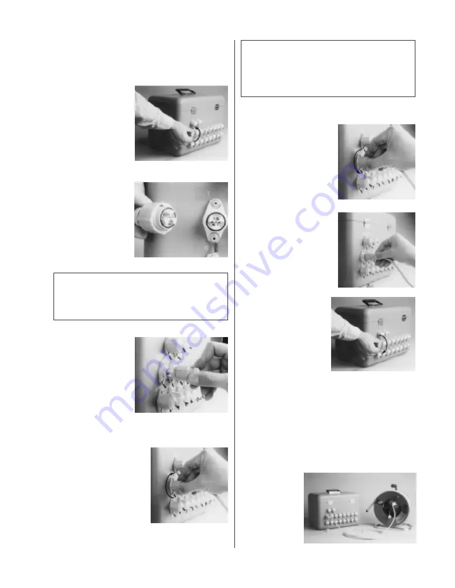
Cables and accessories may be installed or removed as often as your
needs require. To install connectors, observe the following proce-
dures.
1. Remove the protective
cap from the rear panel
connector. If the mating
cable or accessory has a
protective cap, remove it
also.
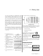
2. Orient the connector pat-
terns so that the large tab
in the cable or accessory
connector is up.
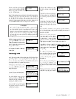
3. Gently press the connec-
tor halves together. Ex-
cessive force should not
be required.
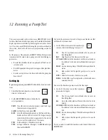
4. Tighten the connector’s lock
ring to establish a tight connec-
tion and water-resistant seal.
To remove a connector, observe the following procedure.
1. Loosen the connector’s lock
ring.
2. Gently pull the connector
halves apart. Store the cable or
accessory in its original con-
tainer or where it will be safe
from damage to the contacts.
3. Replace the protective cap on
the instrument connector.
Transducer Installation
Transducers can be installed at any of the input channel connectors
on the rear panel of the HERMIT 2000. Transducers are typically
installed consecutively beginning at input channel one. The HER-
MIT 2000 must then be programmed to identify the type and char-
acteristics of each transducer connected.
Transducers mounted on reels are supplied with a jumper cable for
convenient connection to the instrument. Transducers on cable
without a reel con-
nect directly to the in-
strument without a
jumper cable.
CAUTION
Proper operation of a transducer or accessory is dependent
upon a clean, dry connection. Make certain that connectors
are clean and dry before attempting to install them.
CAUTION
If a connector jams during installation, it may be upside
down or blocked by dirt or other foreign objects. Attempting
to force it further may result in damage to the connector or
instrument.
Appendix B: Installation, Maintenance & Service


