background image

— 3 —

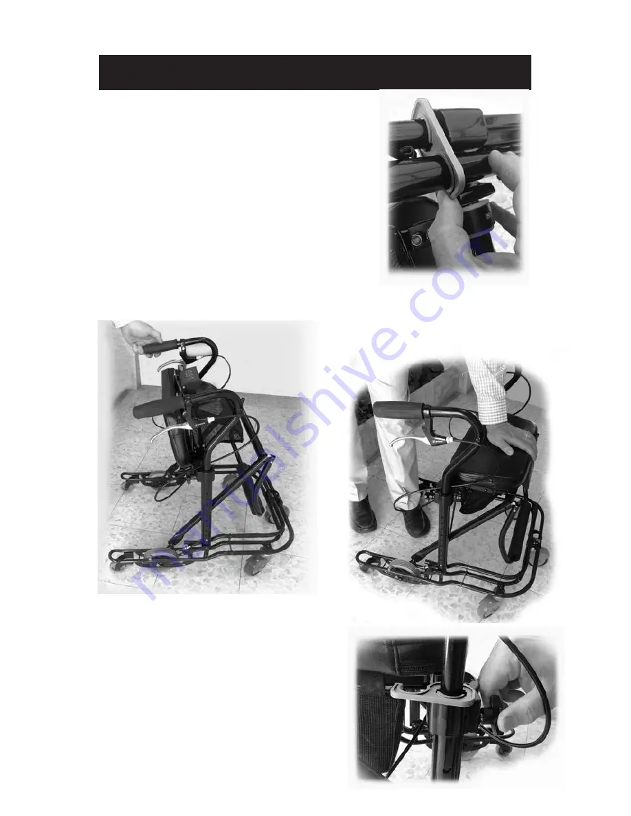
A.  Assembly Instructions

1) Open the box and take out the

U-Step 2 from the box. 

2)  Cut  any  plastic  ties  and  remove

packing material used for protecting

the walker in shipping.

3) Release the locking clip.

Then, press the seat down until it

snaps into place. 

(Below)

5) 

Adjusting the Handlebars

to the

proper height. Generally, the handle-

bars are adjusted so that the handles

are 2-3 inches above your palm when

your arm rests at your side. 

a.  Loosen  the  height  adjustment

knobs  on  both  the  left  and  right

about two turns.

4) Pull up the handle bars until the seat becomes perpendicular

to the ground.

(Below left)

Summary of Contents for U-Step 2 Walking Stabilizer

Page 1: ...arking casters Padded seat Tension control Height adjustment knob Battery pack Backrest Spring loaded front wheel Place to step for going up curbs Glow in the Dark tabs Laser projected red line optional Ergonomically positioned handlebars Comfort grips Cueing module optional Hand brake Basket Locking clip ...

Page 2: ...justment D Sitting Down E Walking Over Obstacles F Transporting G Setup After Transporting H Optional Accessories 1 Laser Sound Cueing Module Replacing the Cueing Module Batteries 2 Weights I Maintenance J Warranty Information Guide for Setting Up Using Your U Step 2 ...

Page 3: ...lip Then press the seat down until it snaps into place Below 5 Adjusting the Handlebars to the proper height Generally the handle bars are adjusted so that the handles are 2 3 inches above your palm when your arm rests at your side a Loosen the height adjustment knobs on both the left and right about two turns 4 Pull up the handle bars until the seat becomes perpendicular to the ground Below left ...

Page 4: ...utton and pull up on the handle bar until the handle bars are the appropriate height c Re tighten the height adjust ment knobs with enough force that the handle bars do not wiggle B Braking The U Step 2 wheels will not roll until you disengage the brakes Squeeze either or both hand brake levers to disengage the brakes To stop release the hand brake levers and the brakes will quickly engage 4 ...

Page 5: ... tension Re tighten the tension locking bolt making sure the lever settles into one of the set holes Note If you do not position the lever in a set hole the tension lever might rub against the side of the gray wheel 4 Remember to squeeze one of the hand brakes while testing the walker Test the rolling speed of the walker if you need more or less resistance adjust accordingly Tension Locking Bolt T...

Page 6: ...acles as high as one half inch D Sitting Down To sit down you can either turn around while holding the handlebar or pivot the U Step 2 around so that it is positioned behind you then sit down on the seat When you are sitting on the U Step 2 you are facing backwards relative to the forward moving direction when walking WARNING j While sitting DO NOT push off with your feet to move the U Step 2 This...

Page 7: ...izontal bar that has a sticker on it reading Lift Here to Fold until the U Step 2 folds up Release Lever 1 With the U Step 2 in front of you raise the release lever in front of the seat and tilt the seat upward F Transporting Your U Step 2 ...

Page 8: ...e U Step 2 in the folded position 2 Allow the U Step 2 to open with the base on the ground 3 Press the seat down in the middle until the Release Lever snaps into place 3 Secure the locking clip to stop the walker from folding Simply rotate the clip until it at taches to the backrest tube 4 Hold the U Step 2 by the side to place it into your vehicle SAFETY NOTE ...

Page 9: ...od before auto matic laser shutoff to conserve battery power and the lower black button adjusts the clicking volume Pressing the upper button extends the shutoff period from 4 to 28 minutes in increments of 4 minutes each click that sounds after pressing the button indicates 4 min utes of operating time in effect from 1 to 7 clicks Pressing the lower button lowers the click volume in steps to the ...

Page 10: ...on of the two batteries Figure 2 ensuring that the the and sides are installed in opposite directions The unit will click either three or five times when the batteries are installed correctly If the unit clicks three times it is shut ting off If the unit clicks five times it is turning on and the power indicator will blink Installing and Replacing the Cueing Module Batteries Figure 1 Figure 2 When...

Page 11: ...device In the event of a problem you will need to return the walker for repair at your cost We will fix the product or replace it and send it back to you at our cost This warranty does not cover device failure due to owner s mis use or negligence In the event of a minor problem In Step Mobility Products will attempt to resolve the issue by sending replacement parts If you have a question about you...

Page 12: ...fications Model US PC2 Model number US PC2 Medicare code HCPC E0147 Weight capacity 161 kg 355 lbs Height adjustment range accommodates users 4 10 to 6 2 Height customization available Size of Padded Seat 19 x 8 Height from floor to seat 22 Overall width 23 Length 25 Folded dimensions approx 42 x 23 x 10 Turning circle 29 Weight 9 5 kg 21 lbs Material of frame Tubular Steel and Aluminum Patent Pen...

Reviews: