08
Deutsch
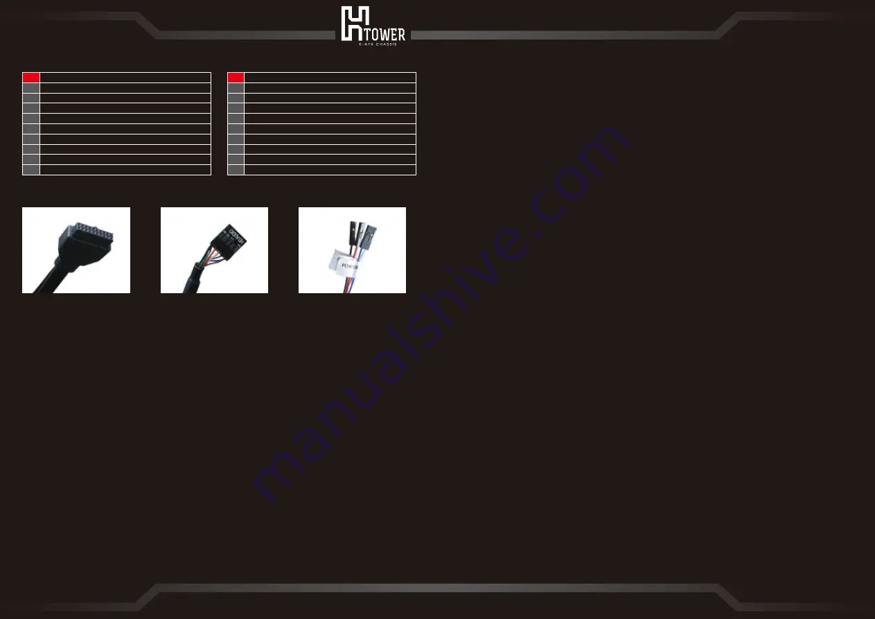
1. Kabel für I/O-Ports an der Frontblende:
1-a
. USB 3.0, Typ A & USB 3.1, Typ C, 19-poliger Anschluss
1-b
. HD-Audiokabel
1-c
. Schalter/LED-Anschluss
2. Damit Sie Hardware optimal installieren können, muss der Motherboard-Montagebereich auf
eine horizontale Position
ausgerichtet sein; dies verhindert Kollisionen und Druck auf den Hauptrahmen.
3. Achten Sie darauf, dass während der Montage nichts in die Lücken der Basis fällt.
4. Die Gewichtsbeschränkung des Motherboard-Rahmens beträgt 10kg.
5. Kabelverwaltungsbereich: Achten Sie zur Gewährleistung eines ungehinderten Betriebs der
Flügel darauf, dass Kabel nicht in den
Sperrbereich gelangen. Befolgen Sie idealerweise die gestrichelte Linie der Kabelverwaltung.
日本語
1. 前方出力/入力ポートケーブルについて
1-a
. USB3.0 Type A & USB3.1 Type C, 19-pin プラグ
1-b
. HD Audio オーディオケーブル
1-c
. 電源および LED ケーブルプラグ
2. 部品組み付けの際は、必ずマザーボードラックを水平にして最良の操作状態にしてください。瞬間的に
重圧をかけたり、マザーボードラックや周囲のファンにぶつけたりしないでください。
3. 部品組み付けの際は、ケース台座の隙間に異物が落下しないように注意してください。
4. マザーボードラックに搭載できる部品の総重量は10キロ以下です。
5. ケーブル管理区域:ケーブルをまとめる際は機器カバーが開く際に影響をおよぼさないよう、ストライ
プの区域を避けてください。点線に沿ってケーブルをまとめることを推奨します。
繁體中文
1. 前置輸出/入埠線材說明
1-a
. USB3.0 Type A & USB3.1 Type C, 19-pin 接頭
1-b
. HD Audio 音源線
1-c
. 電源及 LED 線材接頭
2. 組裝系統配件時請務必讓主機板架呈現水平為最佳操作狀態,不可瞬間重壓或碰撞主機板架及四周葉片
3. 組裝系統配件時請避免異物掉落機殼底座間隙內
4. 主機板架可承載之系統配備總載重量在10公斤以內
5. 理線區域:理線時請避開條紋區域,以避免影響機器開闔,建議沿著虛線指示理線為佳
简体中文
1. 前置输出/入埠线材说明
1-a
. USB3.0 Type A & USB3.1 Type C, 19-pin 接头
1-b
. HD Audio 音源线
1-c
. 电源及 LED 线材接头
2. 组装系统配件时请务必让主机板架呈现水平为最佳操作状态,不可瞬间重压或碰撞主机板架及四周叶片
3. 组装系统配件时请避免异物掉落机箱底座间隙内
4. 主机板架可承载之系统配备总载重量在10公斤以内
5. 理线区域:理线时请避开条纹区域,以避免影响机器开合,建议沿着虚线指示理线为佳
07
Internal Structure
English
1. Front panel ports I/O wires included:
1-a
. USB3.0 Type A & USB3.1 Type C, 19-pin Connector
1-b
. HD Audio Cable
1-c
. Switch/LED Connector
2. For the best hardware installing condition, the motherboard mounting area must be set to a
horizontal position to prevent any collision and instant pressure on the main frame.
3. Prevent objects from falling into the gaps of the base during assembly.
4. The weight limit of the motherboard frame is 10kg.
5. Cable management area: avoid cables from entering the exclusion area for proper operation of
the blades.
Follow the dash line for cable management is recommended.
Français
1. Ports du panneau frontal/ câbles I/O fournis :
1-a
. USB 3.0 de type A & USB 3.1 de type C, Connecteur à 19 broches
1-b
. Câble audio HD
1-c
. Commutateur/ Connecteur de DEL
2. Pour la meilleure condition d'installation matérielle, la zone de montage de la carte mère doit
être réglée à une position horizontale afin d'éviter toute collision et une pression instantanée
sur le cadre principal.
3. Éviter la chute d'objets dans les espaces de la base pendant l'assemblage.
4. La limite de poids du cadre de la carte mère est de 10kg.
5. Zone de gestion du câble : éviter que les câbles d' entrer dans la zone d'exclusion pour favoriser
le bon fonctionnement des lames.
Nous vous suggérons de suivre la ligne pointillée pour la gestion des câbles.
Operating Instructions and Notices
1-a
1-b
1-c
10
11
12
13
14
15
16
17
18
19
風扇 / 水冷排安裝區
2.5吋磁碟盤
主機板安裝區
介面卡PCI-E擴充槽
電源供應器安裝區
升降平台
機殼底座
3.5吋磁碟盤
限量編號
理線區域
风扇 / 水冷排安装区
2.5英寸磁盘盒
主机板安装区
适配卡PCI-E扩充槽
电源供应器安装区
升降平台
机箱底座
3.5英寸磁盘盒
限量编号
理线区域
10
11
12
13
14
15
16
17
18
19
繁體中文
简体中文


