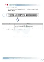
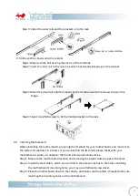
background image


- 14 -


2.8


Reverser IO 


IW-RF100S features IO interface direction reversible, which allows user turn the IO to the front 

and deploy the appliance easily. It only needs to take few steps to change the factory default rear 

IO access to front IO access.


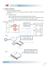
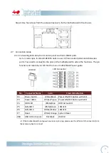
Step 1: Remove the top cover.


Step 2: Unload the power supply unit and unscrew the control panel module; switch the position.


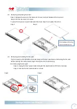
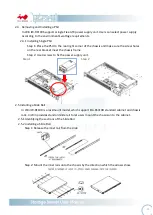
Step 3: Unscrew to remove the fan wall, reverse to change the airflow direction.


Step 4: Remove the handle of both sides, and mount on the opposite end to let the handle face 

the rear side.


3


Compatibility Lists


To reach best performance and avoid system failure, In Win strongly recommend users choosing the 

components from In Win’s compatibility list. All the components are tested in In Win’s lab and assured 

the components are working well with In Win’s chassis.


You can download the latest updated device compatibility list from In Win’s website:


https://www.in-win.com/en/ipc-server


4


Q&A


1.


Is it possible to add front cover? 

You may adapt IW-RS104-

02M’s 1U front cover, but it will block the USB ports and lights in rear access, 

and block the IO ports in front access mode, which is not realistic. 


2.


Do the chassis support mirrored OS disks? 

You can mirror any two hard drives, such as IW-

RF100’s two 2.5” hard drives, or IW

-

RF100S’ two 3.5” 

and two 2.5” drives. Yet, the disk mirroring is defined by your 

motherboard or your RAID 1 controller 

card. You may check the vendor’s guide to mirror your OS disks.


3.


Can it support form factor MB such as M-ATX? 

In Win IW-RF100 supports motherboard range from Mini-ITX to ATX. Unless you would like to mount a 
customized 

motherboard which is not meet Intel’s standard, you will need to contact In Win partners 

or sales for customization service. 

Summary of Contents for IW-RF100

Page 1: ...IW RF100S User s Manual...

Page 2: ...Fan Module P 11 2 3 1 Removing a Fan Module P 11 2 3 2 Installing a Fan Module P 11 2 4 Removing and Installing a PSU Module P 12 2 4 1 Removing a PSU Module P 12 2 4 2 Installing a PSU Module P 13 2...

Page 3: ...designed to operate in a typical office environment The location should be a clean dry and free of airborne particles a well ventilated room and away from sources of heat including direct sunlight and...

Page 4: ...is a short length of conductor used to close open or bypass part of an electronic circuit Jumpers on In Win backplane have a small tab on top that you can pick up with your fingertips Grip the jumper...

Page 5: ...Internal 2 5 HDD x 2 3 5 HDD x 2 Optional 2 5 HDD x 4 Power Supply Supports Form Factor Flex Watt Single 265W or 315W Indicator Power Status HDD LAN Activity LEDs Front Control Panel Power Switch Syst...

Page 6: ...5 1 Product Introduction 1 1 Box Content When you open the carton box of IW RF100S the contents should include...

Page 7: ...l Information When you open the top cover should be like the diagram shows bellow Top cover Single module power supply PWM Fan x 2pcs max to 3 pcs Mini ITX or ATX M B Front Controls and indicators 2 x...

Page 8: ...devices connection 2 Power ON OFF Button Blue Solid on System is powered on Off System is not powered on 3 Power LED No LED function Press the button to activate Power LED 4 Hard Disk LED Green Blinki...

Page 9: ...on cards slot No Name Description 1 Power Supply Window This window is for installing single PSU please reference In Win compatibility list to select the compatible models 2 System I O depend on M B s...

Page 10: ...to remove disk cage Step 2 Populate the 2 5 drive on the cage and fix it with 4 screws from the bottom Stake a 3 5 hard drive on top and screw it up with 4 screws from both sides Step 3 Put back the d...

Page 11: ...on Step 1 Step 2 2 3 Removing and Installing the fan wall The fan module of IW RF100S is tool less design with easy swap feature Removing the fan wall before posting the motherboard to get more space...

Page 12: ...bracket meet the chassis frame Step 2 Use 4 screws to fix the power supply unit Step 1 Step 2 2 5 Installing a Slide Rail In Win IW RF100 is a rackmount model which support EIA RS310D standard cabinet...

Page 13: ...fore installing the motherboard preparing the IO shield for your motherboard and mount it to the system IO window 1 2 2 shows If you cannot find the IO shield please check with your motherboard vendor...

Page 14: ...in function and location you can find from your motherboard s user guide If the motherboard s led power source is 3 pin type please use the 2Pin to 3Pin convertor form the accessory box to connect No...

Page 15: ...ured the components are working well with In Win s chassis You can download the latest updated device compatibility list from In Win s website https www in win com en ipc server 4 Q A 1 Is it possible...

Reviews: