- 1 -
Table of Content
PREFACE
P.2
SAFETY INFORMATION
P.2
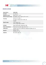
SPECIFICATIONS
P.4
1
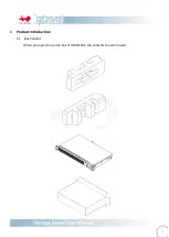
Product Introduction
1.1
Box Content P.5
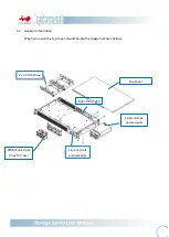
1.2
General Information P.6
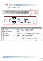
1.2.1
Front Panel Controls and Indicators P.7
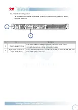
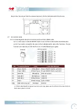
1.2.2
Rear Panel Configuration P.8
2
Hardware Installation
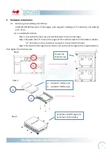
2.1
Removing and Installing a Hard Drive P.9
2.1.1
Installing a Hard Drive P.9
2.1.2
Removing a Hard Drive P.9
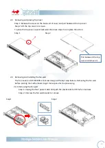
2.2
Removing and Installing Top Cover P.10
2.3
Removing and Installing a Fan Module P.11
2.3.1
Removing a Fan Module P.11
2.3.2
Installing a Fan Module P.11
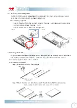
2.4
Removing and Installing a PSU Module P.12
2.4.1
Removing a PSU Module P.12
2.4.2
Installing a PSU Module P.13
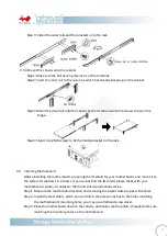
2.5
Installing Slide Rail P.13
2.5.1
Identifying the slide Rail P.13
2.5.2
Take out the inner rail and slide the intermediate rail back P.13
2.5.3
Attach the inner rail to the chassis P.14
2.5.4
Mount the rail bracket to the cabinet P.14
2.5.5
Insert the chassis to the cabinet P.15
2.6
Installing Motherboard P.16
2.7
Connecting Cable P.17
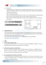
3
Backplane Introduction
P.18
4
Compatibility Lists
P.20
5
Q&A
P.20
6
Technical Support
P.23
Summary of Contents for IW-RF100
Page 1: ...IW RF100S User s Manual...


