20
No.
Connector Name Abbreviation
Color
Front IO Indication
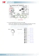
CONN2 Power LED
PW LED
WHITE/BLACK Power ON/OFF Button with LED
CONN3 Alarm LED
SYS LED
WHITE/GREY System Fail LED
CONN4 ID LED
ID LED
WHITE/BROWN Chassis ID Button with LED
CONN5 LAN 1 LED
LAN1 LED
WHITE/RED
LAN LED
CONN6 LAN 2 LED
LAN2 LED
WHITE/ORANGE LAN LED
CONN7 LAN 3 LED
LAN3 LED
BLACK/RED
LAN LED
CONN8 LAN 4 LED
LAN4 LED
BLACK/RED
LAN LED
CONN9 Power Switch
PW SW
WHITE/YELLOW Power ON/OFF Button with LED
CONN10 NMI Switch
NMI SW
WHITE/GREEN NMI Button
CONN11 Reset Switch
RESET SW
WHITE/BLUE
System Reset Button
CONN12 ID Switch
ID SW
WHITE/PURPLE Chassis ID Button with LED
-
USB 3.0 Connector None
-
USB 3.0
-
Mute Switch
Mute
-
Mute Switch
3
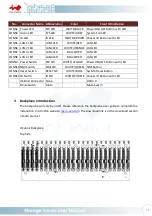
Backplane Introduction
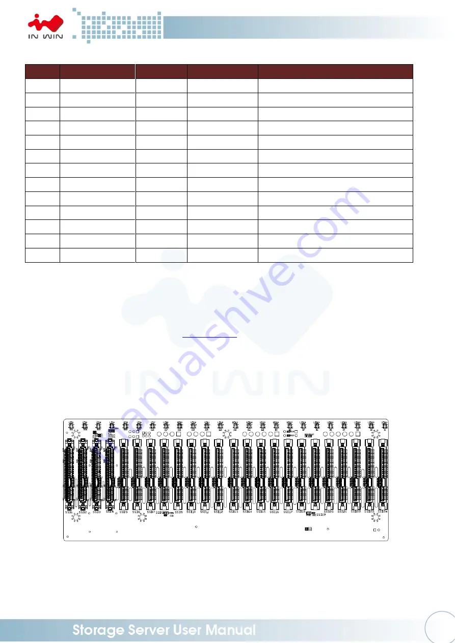
The backplane will vary by order. Please reference the backplane user guide to complete the
installation. Visit InWin website:
ipc.in-win.com
. The download link is at the download section
of each product.
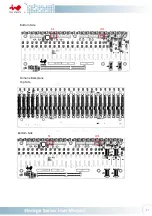
OCuLink Backplane
Top Side

