-
16
-
2.7
Connection Cable
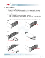
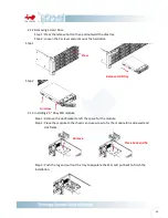
2.2.1
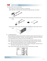
Connecting backplane through SAS connectors
In Win IW-RS316-02M needs SAS cable connecting the backplane and your motherboard or
RAID controller. In Win provides verified SAS cable for installation, please contact In Win
local partners and sales to get more information.
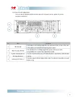
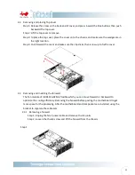
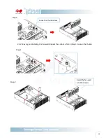
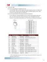
2.7.2
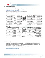
Connecting LED cable, front control panel and front USB IO ports
As 1.2.1 descripts, In Win IW-RS-02M built-in a set of front control panel and USB access
ports. You need to cover the connectors to the pins on the motherboard to active the
functions. The pin function and location you can find from your motherboard’s user guide.
※
If the motherboard’s led power source is 3-pin type, please use the 2Pin-to 3Pin convertor form
the accessory box to connect.
No.
Connector Name
Color
Front IO Indication
P2
NMI Switch
Black/Brown
NMI Button
P3
Reset Switch
Red/Orange
Power Reset Button with LED
P4
LAN LED 4
Yellow/Green LAN LED
P5
LAN LED 3
Blue/Purple
LAN LED
P6
LAN LED 2
Gray/White
LAN LED
P7
LAN LED 1
Black/Brown
LAN LED
P8
HDD LED
Red/Orange
HDD Active LED
P9
System LED
Yellow/Green System Fail LED
P10
ID LED
Blue/Purple
Chassis ID Button with LED
P11
ID Switch
Gray/White
Chassis ID Button with LED
P12
Power LED
※
Black/Brown
Power ON/OFF Button with LED
P13
Power Switch
Red/Orange
Power ON/OFF Button with LED
USB
USB 3.0 Connector
Black Flat
USB 3.0
USB 3.0
LED Connector
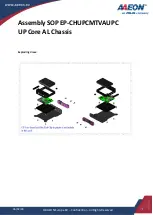
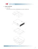
Summary of Contents for IW-RS316-02M
Page 1: ...IW RS316 02M User s Manual...