background image


PAGE 14

 Pty Ltd

TPMS-4WD-V2 

User and installation guide

Document 913-9001 Rev G  11/July/2012

Copyright 2009   @ll rights reserved 

This document is not to be reproduced or copied in ^ny w^y unless the express permission in writing h^s been obt^ined 

from 

In^wise Pty Ltd

 (@ustr^li^) 


3.5 

Turning on the Sensor/Transmitters 

The sensor units are shipped in a powered down sleep mode to conserve battery 
life and ensure maximum battery life once they are put into service.  

The sensors are activated from the “power down shipping mode” by 
pressurising the sensor or driving the vehicle with the sensors installed on the 
wheels at a speed of 25km/h or more for a few minutes


As the sensors come on-line the display will change from displaying “000” to 
displaying the data for that wheel.  


3.6 

Checking the system works 

The system should now be up and fully functional.  All four readings on the 
displays should be showing the correct tyre pressure for all four tyres.  

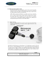
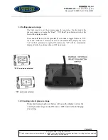
By pressing the “function” button located at the front of the display, the display 
should first turn on the LCD backlight. A second press will cause the display to 
toggle from pressure display to temperature. 


The LCD backlight will stay on for only a few seconds and then automatically 
turn off again to preserve power. 


“Function” Button

Summary of Contents for TPMS-4WD series

Page 1: ...Productfeaturesandinstallationinstructions fortheTPMS 4WD V2tyrepressureand temperaturemonitoringsystem Document Number 913 9001 Rev G 11 July 2012 User and installation guide TPMS 4WDseries TyrePress...

Page 2: ...1 2 1 Cigarette lighter power option 6 3 1 2 2 Hard wired power option 6 3 1 3 RF Antenna 7 3 1 3 1 Wire Antenna 7 3 1 4 Fixing display module into place 8 3 1 5 Reconnect vehicle battery 8 3 2 INSTA...

Page 3: ...L 16 5 2 TURNING ON LCD BACKLIGHT 16 5 3 DISPLAYING TYRE TEMPERATURE 17 5 4 DISPLAYING SENSOR KEY ID 17 5 5 DISPLAYING CURRENT PRESSURE RANGE 17 5 6 SETTING BASE PRESSURE 18 5 7 ROTATING TYRES 18 5 8...

Page 4: ...designed for 4WD vehicles catering to the unique requirements imposed by 4WD applications One of the features of this model is a Low and High range pressure selector switch on the back of the display...

Page 5: ...years typical or 250 000km of driving The concept being that if a set of sensors is fitted to a vehicle at the time that a new set of tyres are fitted the sensors will outlast the life of the tyres A...

Page 6: ...ure Audible and visual alert on under pressure Audible and visual alert on fast leak detection over 3 7 PSI within a 15second period Audible and visual alert on over temperature Display unit powered f...

Page 7: ...sor s ID is associated with an ID Key which is a device which looks like a button and plugs into the side of the display module This ensures only information from the correct sensors is read and displ...

Page 8: ...sional it is time consuming and hard work without the correct equipment In addition on completion the wheels need to be dynamically balanced which can only be done with the appropriate tyre balancing...

Page 9: ...can tap into the 12V supply Remember the supply must be permanently on even when the ignition is turned off Normally the vehicles stereo system uses such a supply for the clock function Next disconne...

Page 10: ...sitioned so that a reliable level of signal reception is obtained 3 1 3 1 Wire Antenna Run the two wire antennas in opposite directions across the dash or preferably hidden under the dash and around t...

Page 11: ...Fixing display module into place Fix the display module into place using the double sided adhesive supplied Ensure both surfaces are clean and if necessary clean with methylated spirits 3 1 5 Reconnec...

Page 12: ...learance suitable to install the sensor module This method reduced the time required as the tyre does not have to be completely removed from the rim Care must be taken to ensure the tyre wall does not...

Page 13: ...s for the sensor transmitters have been identified they can be fitted to the rims 3 2 2 Sensor Disassembly Remove the Valve Cap and the Retaining Nut from the valve stem The Retaining Nut has a plasti...

Page 14: ...the angle of the electronics module so it sits as close as possible to the rim surface preferably hard against it then tighten the Self locking screw to lock the electronics module into that position...

Page 15: ...e rim 3 2 7 2 Position tyre The lower bead must be mounted with the mounting head of the changer located at 12o clock while the position of the tyre valve is at 7 o clock This is done to ensure the el...

Page 16: ...e range is set using the Road Off Road push button switch at the back of the display module Press and hold the switch for aproximatly 6 seconds to toggle betweeon ON road and OFF road modes The screen...

Page 17: ...e sensor or driving the vehicle with the sensors installed on the wheels at a speed of 25km h or more for a few minutes As the sensors come on line the display will change from displaying 000 to displ...

Page 18: ...itters being damaged 4 1 Breaking upper and lower bead The upper and lower beads must be broken with the bead breaker head located AT LEAST 90deg of arc away from the tyre valve sensor transmitter mod...

Page 19: ...display and holding down for 6 seconds until you hear a beep indicating the pressure mode has been changed The tyres can then be deflated to the required pressure determined by the terrain When going...

Page 20: ...dition to the labels A B C and D each transmitter sensor has a unique 6 digit identifier Pressing and holding down the Function button on the font of the display module for 8 seconds will cause the di...

Page 21: ...t the tyre readings are displayed in the correct locations on the LCD Step 1 Physically rotate the wheels on the vehicle as required Step 2 Turn the On Off switch on the back of the display module to...

Page 22: ...replaced Replacement sensors are available from Inawise Pty Ltd Step 1 Remove the wheel from the vehicle and remove the tyre as described in Section 4 Tyre Removal Step 2 Remove the old sensor from t...

Page 23: ...i 6 Displays and Warnings Low Pressure Warning Warning Threshold Alerts Below 11 6psi in Off Road mode Or Below 27 5psi in On Road mode 1 Audible beep 2 Display Backlight turns ON 3 Problem indicator...

Page 24: ...ed from In wise Pty Ltd ustr li High Temperature Warning Warning Threshold Alerts Temperature above 80DegC 1 Audible beep 2 Display Backlight turns ON 3 Problem indicator ICON is displayed 4 Border ar...

Page 25: ...e ID module is not properly connected with the display Carry out ID module Check Section 5 4 System Lock up Switch the rear Power switch to OFF then ON is displayed even when you drive faster than 25k...

Page 26: ...located at the back of the display module 3 Can I use TPMS with my Nitrogen inflated tyres Absolutely Yes Nitrogen will make the pressure inside the tyre more stable and reduce tyre aging It is possib...

Page 27: ...ressure and temperature seem to be constantly changing from one moment to the next Is there a problem with the system No the readings are the actual tyre pressures at that instant Normally the tyres o...

Page 28: ...econds When the car is stopped or travelling at low speed the system samples data at longer intervals in order to extend the sensor transmitter battery life 15 How long does it take to install the com...

Page 29: ...of around 1 5psi The sensors used by Inawise are manufactured by GE General Electric and are considered high accuracy with a tolerance of 0 75psi It is most likely that the reading given by the Inawis...

Page 30: ...manufacturer Shanghai Baolong Industries Corporation China through Inawise Pty Ltd Australia The warranty is limited to the parts only and does not cover any labour or material whatsoever including bu...

Page 31: ...t threshold 27 5psi High pressure lert threshold 55psi High temper ture lert threshold 80DegC Intern tion lly p tented ID Key module technology en bles tyres to be e sily rot ted nd or repl ced CE FCC...

Page 32: ...from entering the valve step body and fouling the air valve The plastic caps have been selected to eliminate the possibility of corrosion due to electrolysis between the aluminium body of the valve st...

Reviews: