Pa
ge
3
2. Installation
Switch off ignition and disconnect the vehicle’s battery! If according to factory rules
disconnecting the battery has to be avoided, it is usually sufficient to put the vehicle in
sleep-mode. In case the sleep-mode does not show success, disconnect the battery with a
resistor lead.
2.1.
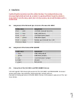
Assignment of the female12-pin connector of harness RLC-CX011
Cable colour
Assignment
Pin 1
●
pink
+12V ACC (output) max.1.5A
Pin 2
●
blue
CAN-LOW (input)
Pin 6
●
red
+12V Permanent (input)
Pin 8
●
yellow
CAN-HIGH (input)
Pin 9
●
green
Reverse gear (output) max. 1.5A
Pin 12
●
black
Ground
2.2.
Assignment of the harness PNP-QUAD01
Cable colour
Assignment
●
blue
CAN-LOW (output)
●
yellow
CAN-HIGH (output)
●
red
+12V Permanent (output)
●
black
Ground
●
green
No function
2.3.
Connection of the RLC-CX011 and PNP-QUAD01 harness
Connect together the following loose wires of the RLC-CX011 and PNP-QUAD01 harnesses:
yellow with yellow, blue with blue, black with black and red with red.
Connect the loose green wire on the RLC-CX011 harness to the power supply wire of the rear
view camera.


