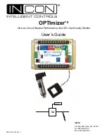
background image

OPTImizer

®


2

 On-Line Circuit Breaker Performance And SF

6

 Gas Density Monitor

User’s Guide

52

OPTImizer

©2012 000-1530 Rev C 

INCON

P.O Box 638, Saco, Me. 04072 

Tel: 207-283-0156 

Fax: 207-238-0158

Summary of Contents for OPTImizer 2

Page 1: ...OPTImizer 2 On Line Circuit Breaker Performance And SF6 Gas Density Monitor User s Guide 52 OPTImizer 2012 000 1530 Rev C INCON P O Box 638 Saco Me 04072 Tel 207 283 0156 Fax 207 238 0158 ...

Page 2: ...his device on the power system there is always the possibility of faulty equipment operation and electrical shock Any of these situations may result in injury or death Return Shipping Charges INCON will not accept shipments of returned products without a Return Goods Authorization RGA number RGAs are obtained by contacting INCON s Technical Service Division NO RGAs will be given without the unit s...

Page 3: ...NP3 0 SETTINGS 35 CIRCUIT BREAKER INFORMATION 36 4 3 Circuit Breaker Monitor Settings 36 Input Mode 41 Contact Wear Mode 43 If breaker is Rated in MVA and is being Applied at Voltage other than Nameplate 45 Contact Life Warning Limit 45 Trip Time Alarm Limit 45 Arc Time Alarm Limit 46 Clearing Time Alarm Limit 46 Travel Time Alarm Limit 46 Closing Time Alarm Limit 46 Operations Count Alarm Limit 4...

Page 4: ...rt 58 SF6 Daily Summary Report 58 Data Interpreting 58 5 3 Alarm Acknowledgement Cancellation 60 5 4 USB Scripts 60 6 COMMUNICATION DETAILS 61 6 1 RS 232 61 6 2 Fiber Optic Interconnection 63 6 3 RS 485 63 6 4 Ethernet 63 6 5 XML 64 6 6 DNP3 0 66 6 6 1 Device Profile Document 66 6 6 2 DNP3 0 Implementation Table 68 6 6 3 DNP3 0 Point List 69 7 SPECIFICATIONS 72 DSDP SF6 Density Temperature Sensor ...

Page 5: ...ge 38 Figure 15 Aux A Interface using Individually Wetted 52 a Contact 39 Figure 16 Aux B Interface using Green Light 39 Figure 17 Aux B Interface using 52 b Contact in Green Light Circuit 40 Figure 18 Aux B Interface using Individually Wetted 52 b Contact 40 Figure 19 Trip Trace illustrating A Input Delay Setting Considerations 41 Figure 20 Estimated Trip Latch Release Times based on Nameplate Br...

Page 6: ...s 16 Table 3 Alarm Set points 26 Table 4 Alarm Outputs LED s and Relays 26 Table 5 Impact of A Input Assertion on the A Input Delay Setting 42 Table 6 Must Clear Times of Breakers Voltage Dependent 43 Table 7 Accumulated Duty Wear Calculation Example based on Trip History 52 Table 8 Alarm Codes 55 Table 9 Application Event Codes 56 Table 10 OPTImizer2 Specifications 72 ...

Page 7: ... oil and vacuum breakers The wear models used in the OPTImizer2 are valid for any voltage class and correspond to ANSI IEEE C37 06 1989 1 2 Operation Overview CONDITION and WEAR LOGGING SF6 Density g L Pressure PSIG BAR Kilopascals Mass Pounds Kilograms SF6 Trend Rate units day Mass Loss Pounds Kilograms Pounds CO2 Metric Tonnes CO2 Trip Time mS Duration of the arcs by phase during tripping mS Cle...

Page 8: ...eaching an alarm setpoint or detecting a failure mode These may be reset by software command The circuit breaker OPEN CLOSED status is also shown by green and red LEDs on the OPTImizer2 This OPEN CLOSED status indicator should only be used as a secondary indication and to verify correct programming of A INPUT POLARITY and B INPUT POLARITY assertion states An LED bar graph alternates every 10 secon...

Page 9: ...ical Services USB COMMUNICATION PORT This port is for data dumping BIN files and ASCII text files alarm acknowledgement or firmware upgrades It will Interface only to a USB memory stick A memory stick with a special software tool can be used to acknowledge alarms This software tool can be downloaded from the OPTImizer2 Product CD A memory stick containing a special upgrade script and files can be ...

Page 10: ...mended 90 264 VAC 50 60Hz Use Twisted Pair Cable Contact Rating 3A 250 VAC or 1 2A 125VDC The OPTImizer2 should be installed as close to the CT Pickup Coils as possible Cut any excess cable from the Pickup Coils It is not recommended to extend the Pickup Coil cables SF6 Density Sensors Terminal Screw maximum torque 12 inch Lbs ...

Page 11: ...11 2 2 Mounting Dimensions Figure 2 OPTImizer Mounting Dimensions Not actual size ...

Page 12: ...12 Figure 3 OPTImizer General Dimensions ...

Page 13: ...e critical to mount this type of sensor as close as possible to the SF6 gas vessel so that the temperature of the SF6 gas can properly affect the sensor A difference in temperature between the SF6 gas in the vessel and a sensor of this type will cause an error in the density output signal The SF6 density sensor may be installed alongside an existing SF6 density switch or gauge If only one opening ...

Page 14: ...rip Trace ANSI Standards C37 06 A Input Delay Time Difference between Aux A input and the main contacts parting Breaker Nameplate Data Breaker Manufacturer s Data Sheets Breaker Nameplate ANSI Standards C37 06 Contact Life Mode I2 xT or IxT Contact Life Danger Limit Contact Life Warning Limit Operations Count Limit SF6 Gas Fill Weight SF6 Gas Fill Pressure SF6 Gas Fill Temperature Breaker Volume B...

Page 15: ...sible Cut any excess cable from the Pickup Coils It is not recommended to extend the Pickup Coil cables A B C Aux B Interface Aux A Interface Phase A Snap on CT Phase B Snap on CT Phase C Snap on CT Phase A Snap on CT Phase B Snap on CT Phase C Snap on CT R G Aux A Interface Aux B Interface Bushing CT Typ Phase Relay Typ Ground Relay Typ BREAKER CABINET CONTROL HOUSE or TI TI b aor Figure 5 Breake...

Page 16: ...tances electrical noise step potential Table 2A Breaker Cabinet Installation Considerations Control House Mounting Pros Cons Centralized location for multiple unit installations May lie within an area not readily accessible to Maintenance personnel Trip Initiates red light signal for asserting the Aux A input and an end of mechanism travel green light signal for asserting the Aux B interfaces are ...

Page 17: ...electric Capability The ability of a circuit breaker to extinguish an arc can be monitored by examining the amount of time an arc is present after a trip command to the breaker is given If the mechanism transit time remains constant but an increase in arc duration is noted from a baseline level some dielectric compromise can be assumed to have occurred in the arc chamber Samples of issues that may...

Page 18: ...ice to use the trip initiate or the parting of the 52 a will depend on where the OPTImizer s Aux A input is wired in the circuit The proper A INPUT DELAY must be programmed accordingly The ability to know this time difference allows the OPTImizer2 to precisely start timing the arc for both the arc duration record and the wear duty I2 xT or IxT calculations Reference for the following function desc...

Page 19: ...ng additional interface such as isolating relays and diodes The Aux B input is fused optically isolated and transient protected If it fails it will be open therefore it cannot cause a false indication or short circuit when applied in actual breaker control circuits INPUT MODE The Aux Input logic mode can be programmed for one of four conditions Mode 1 Use this mode when the Aux A B Input voltages ...

Page 20: ... INPUT POLARITY and is application dependent The actual starting of the log is dependent on a setting used to adjust the time interval difference between the Aux A assertion and the actual parting of the mains This adjustment time is referred to as A INPUT DELAY in Figure 6 The A INPUT DELAY value may be either positive or negative depending on if the Aux A assertion is later or earlier than the m...

Page 21: ...ent arc events occur the measured I2 xT or IxT is added to the phase segregated main contact wear duty accumulation logs Note If the CT Secondary phase currents are less than 7 of the Pickup Coil s full scale current rating and the breaker trips an ARC TIME of 000mS will be recorded The values of I2 xT or IxT recorded for such incidents are recorded as 0 in the wear duty log Operations Counter A c...

Page 22: ...ts The phase currents The A INPUT DELAY setpoint The ARC TIME and TRAVEL TIME setpoints The setpoints and applied limits for the following examples are given below each time line Figs 6A 6B 6C and 7 Figure 6A Trip Trace Using Trip Coil Voltage to Start OPTImizer2 TRIP MECHANISM TIME TRIP TIME 24 mS MECHANISM TRAVEL TIME difference between Aux A and Aux B Input state changes 49 mS ...

Page 23: ...S The A INPUT DELAY Setting is 19mS as the assertion to the Aux A input on the OPTImizer2 is the breaker Aux A contact which opens 19mS after the main contacts part A INPUT DELAY is negative when the assertion to the Aux A input is later than the main contacts parting The TRIP TIME alarm limit is 30mS The ARC TIME alarm limit is 48mS 32mS plus 16mS margin The CLEARING TIME alarm limit is 78mS 56mS...

Page 24: ...h this wiring method The recorded TRAVEL TIME is 51ms The recorded ARC TIME is 32mS The A INPUT DELAY Setting is 19mS as the assertion to the Aux A input on the OPTImizer2 is the same Aux A switch which opens 19mS after the main contacts part A INPUT DELAY is negative when the assertion to the Aux A input is later than the main contacts parting The ARC TIME alarm limit is 48mS 32mS plus 16mS margi...

Page 25: ...r2 Example The Aux A input on the OPTImizer2 is asserted by the trip initiate signal red light in the breaker trip circuit The recorded TRAVEL TIME is 94ms The recorded ARC TIME is 32mS The A INPUT DELAY Setting is 24mS as the assertion to the Aux A input on the OPTImizer2 is the trip initiate signal which asserts 24mS before the main contacts part A INPUT DELAY is positive when the assertion to t...

Page 26: ...sabled Alarm Outputs Indications Relay Assertions Upon reaching an alarm setpoint output designations are Alarm LED Relay Contact TRIP TIME Slow Speed Yellow ARC TIME Excess Arc Flashing Red CLEARING TIME Excess Arc Red TRAVEL TIME Slow Speed Flashing Yellow Contact Life Warning Bargraph Slow Flash Yellow Contact Life Danger Bargraph Fast Flash Red Restrike Restrike Red Operation Counts Operations...

Page 27: ... OR OR Red Yellow Blue SF6 Excess Trip Time A B Input Logic Excess Travel Time Operations Count No Operations Excess Closing Time Failed CT Pickup SF6 Low Gas SF6 Signal out of Range Loss of SF6 Sensor SF6 Trend Unknown SF6 Monitor Activity Internal Error Input Invalid Unknown CB Monitor Activity Figure 8 Alarm Relay Assignments ...

Page 28: ...rning and Alarm If the SF6 gas density or pressure decreases the OPTImizer2 will give a warning when a programmable limit is reached The SF6 Alarm LED will light and a time stamped record of the warning will be logged in the history If the SF6 gas density or pressure decreases further a Low Gas Alarm will be activated closing the SF6 Alarm Relay A time stamped record of the alarm will be recorded ...

Page 29: ...s for Communication Before attempting to modify any computer settings contact the Information Technologies department of your business if available Some computer accounts may have restricted permissions to overcome before any changes are allowed to be made to TCP IP settings At the PC Windows XP 1 Log into your PC with Windows operating system 2 Click on Start then select Control Panel In Classic ...

Page 30: ...networks to maximize bandwidth or capacity of medium resources cables or fiber Therefore when your network uses static IP addressing assigned by an administrator this mask must match the Subnet Mask of the router port that it is attached to If the network uses a DHCP server automatically assigns IP addresses then the mask should meet the specifications set by your administrator Default Gateway The...

Page 31: ...31 Windows 7 Below is shown one way to configure the connection using Windows 7 1 Open Windows Explorer and right click on Network 2 Select Properties 3 Select Change Adapter Settings ...

Page 32: ... 4 The screen should show the Local Area Connection Right click on the connection and select Properties 5 Select Internet Protocol Version 4 TCP IPv4 6 Select Properties 7 Enter the IP address 192 12 27 2 ...

Page 33: ... 27 1 in the browser s address field You should see the OPTImizer2 s STATUS page Click Configuration at the top left to move to the CONFIGURATION page Click Edit at the top right to make changes to the OPTImizer2 s configuration Figure 9 User Interface Configuration Page Initial Set up Configuration settings required to initially set up commission or test an OPTImizer2 are included under the follo...

Page 34: ... password initially set to admin will need to be given for the changes to be saved Commissioning the OPTImizer2 involves setting most of the available programming parameters Note that during initial setup and programming alarms may be triggered inadvertently When all configuration programming is done it is recommended to Clear Latched Alarms on the ACTION page to clear alarms and preset the remain...

Page 35: ...twork and perform all user interface functions To access an OPTImizer2 its IP address is needed A new OPTImizer2 is shipped with the default IP address of 192 12 27 1 As part of a network the OPTImizer2 will need a different IP address To change the IP address select the CONFIGURATION tab and click EDIT Program IP Address nnn nnn nnn nnn To change the passwords select the CONFIGURATION tab and cli...

Page 36: ...to 60Hz To set Power System Frequency select the CONFIGURATION tab and click EDIT Power System Frequency The System Frequency is selected from a pull down list BUSHING CT RATIO Entering the applied CT ratio allows the OPTImizer2 to reflect Duty values to the primary base Enter the applied CT ratio to set the OPTImizer2 Primary current to Secondary current Example Given A CT of 1000 5 is applied fo...

Page 37: ...witches SCADA contacts etc With the OPTImizer2 Aux A input wired in parallel with the trip initiates red light the voltage levels sensed by the Aux A input during a trip operation would be as follows Breaker Closed The trip initiates are open the red light is lit as the 52 a contact is closed and a low current is passing through the trip coil The Aux A input would sense voltage Trip Command One of...

Page 38: ...a Contact in the trip circuit should be set as A Input Polarity Positive INPUT MODE 1 or 3 OPTImizer2 Aux A Input R T 2 T 1 52 a TC Closed Open Trip A Input Polarity Positive Figure 14 Aux A Interface using Trip Coil Excitation Voltage This is an elementary diagram of a typical trip circuit The elements T 1 and T 2 are trip initiating contacts These could be from protective relays manual trip swit...

Page 39: ...zer2 to properly stop the mechanism time log The OPTImizer2 reacts to a change in voltage state when the breaker is proceeding from the closed position to the open position These are defined to the OPTImizer2 as No voltage to voltage Positive Voltage to no voltage Negative Note When the OPTImizer2 is cold started the B Input Polarity parameter is set to Positive B Input Polarity The B Input Polari...

Page 40: ... Opened The 52 b contact remains closed and the Aux B input would continue to sense a no voltage condition In summation the OPTImizer2 when applied in parallel with the 52 b contact should be set as B Input Polarity Negative OPTImizer2 Aux B Input 52 b Closed Open B Input Polarity Positive Figure 18 Aux B Interface using Individually Wetted 52 b Contact This is an elementary diagram of an individu...

Page 41: ...ed To set the Input Mode select the CONFIGURATION tab and click EDIT The Input Mode is selected from a pull down list Mode 1 Continuous A Signal with Continuous B Signal Mode 2 Momentary A Signal No B Signal Mode 3 Continuous A Signal No B Signal Mode 4 Momentary A Signal with Continuous B Signal A Input Delay Time Difference between Aux A Input Assertion and Parting of Main Contacts Entering the ...

Page 42: ... setting is the time difference between the opening of the 52 a contact and the parting of the main contacts Use breaker operation time line provided by the manufacturer in Instruction literature provided the 52 a contact has not been adjusted from the manufacturer 4 Series connection to wetted 52 a contact not in breaker trip circuit Use breaker trip trace A Input Delay setting is the time differ...

Page 43: ...cold started the Contact Wear Mode is set to I 2 T To set the Contact Wear Mode select the CONFIGURATION tab and click EDIT The Contact Wear Mode is selected from a pull down list Contact Life Danger Limit The Contact Life Danger Limit is the alarm setpoint for cumulative IxT or I2 T duty This limit is usually correlated to the ultimate wear out of the contacts Breaker manufacturers typically prov...

Page 44: ...rranted Example Given Breaker is rated at 69kV 20kA fault interrupt symmetrical 1200A rated load break No information is given on the number of fault rated interruptions Assume 69kV breakers have an arc duration T of 24mS 0 024s 69kV breaker can withstand 100 rated load break operations NL before an inspection ANSI IEEE C37 06 1989 Calculate NF NL IL IF NF 100 1200A 20kA NF 6 Danger Limit NF I2 xT...

Page 45: ... Warning Limit to 30 of the Danger limit Program Contact Life Warning Limit 30 The OPTImizer2 will automatically calculate the Warning Limit I2 xT Set at One Fault Rated Interruption less than the Danger Limit Setting the Warning Limit at one fault interruption operation allows a Warning alarm to be issued before another fault takes place and brings the breaker cumulative I2 xT to the Danger Limit...

Page 46: ...sables this alarm To set the Clearing Time Alarm Limit select the CONFIGURATION tab and click EDIT Program Clearing Time Alarm Limit 55 Travel Time Alarm Limit The OPTImizer2 will measure the time between the opening of the 52a switch and the closing of the 52b switch if programmed for Input Modes 1 or 4 A Travel Time Alarm Limit can be programmed in milliseconds When the measured Travel Time reac...

Page 47: ...mber of days since the last trip operation A No Operations Alarm Limit can be programmed in days When the number of days since the last trip operation reaches or exceeds this Alarm Limit an alarm will be asserted This limit should be set according to the breaker manufacturer s recommendations Note When the OPTImizer2 is cold started the No Operations Alarm Limit parameter is set to ZERO which disa...

Page 48: ...e Arc No Restrike Arc Time 5 5 Cycles Restrike not detected Possible total arc duration 10 cycles Arc begins here Less than cycle Figure 22B A 5 Cycle Arc No Restrike Arc Time 5 5 Cycles Restrike detected Possible total arc duration 10 cycles Arc begins here More than cycle Figure 22C A 5 Cycle Arc Restrike Detected ...

Page 49: ...t An alarm will be asserted when the density or pressure reaches or falls below the programmed Low Gas Alarm Limit The Low Gas Alarm Limit can be set to the circuit breaker manufacturer s Lock Out Limit specification If the OPTImizer2 is used in conjunction with an electro mechanical gas monitoring device this Alarm Limit can be set higher than the manufacturer s Lock Out Limit specification to pr...

Page 50: ...r the headings SF6 Sensor A SF6 Sensor B SF6 Sensor C Program Signal Low mA 6 5 Analog Sensor Signal Low Represents Units Each SF6 input on the OPTImizer2 can be programmed to scale the analog Signal Low programmed above to a grams per liter value that may be something other than zero Note When the OPTImizer2 is cold started the Signal Low Represents parameter is set to 0 0 g L To set the Signal L...

Page 51: ... be of no consequence to the wear duty of the breaker The general method is to add the total I xT or IxT from all fault operations to the total I xT or IxT from all load breaks for each phase The equation used is similar to the one used to derive the Danger Limit value except that the variables represent individual operations Use the equation WN IN T to determine Duty Wear for each operation where...

Page 52: ...operation number into the field Click Yes to confirm Clear Latched Alarms When an alarm occurs an LED will be lit to give a general indication of what has caused the alarm Table 4 gives a listing of which LED is lit for each alarm Some of the LED s can indicate a number of different alarms To know specifically what alarm is active when an LED is lit browse to the Status page A complete listing of ...

Page 53: ...w SF6 Trend will be calculated for that channel Until there is a full array of data to calculate the new Trend the Confidence Level for that channel will indicate less than 100 To reset the SF6 Trend Data for a channel select the ACTION tab and click Reset SF6 Trend Data and Alarm Channel A B or C A yellow bar will appear at the top of the window Click YES to confirm the action The correct Adminis...

Page 54: ...e viewed graphed sorted as desired See also page 59 for instructions for downloading the complete OPTImizer2 database using a USB Script See pages 54 58 in this manual for a detailed explanation of each item in each report History Log The OPTImizer2 records all alarm events application events circuitbreakereventsandSF6 densitymeasurements in a large History Log database Five types of reports can b...

Page 55: ... Alarms alOperationCountLimit Operation Count Limit Operation Count has reached the Limit On ACTION Tab Reset Operations Counter alNoOperationsTimeLimit No Operations Time Limit Time between CB operations too long Operate the circuit breaker alABLogicAlarm A B Logic Alarm Logic violation on A B inputs Self clears when the A B Input logic is OK alConfigurationCbMonitor Invalid CB Monitor Config CB ...

Page 56: ...occurred Cleared The report indicates the date and time the alarm was cleared Alarms that are presently in the active state will not have a cleared date and time Application Event History Report The Application Event History Report consists of Code Category Device Data Date Time Occurred Code This Code is an abbreviation for the description of the Application Event The prefix ae is used to indicat...

Page 57: ... was recorded because the Operation Counter was reset Operation Number This number is associated with the total operations on the circuit breaker and if correctly preset should match the circuit breaker s mechanical counter Over Trip Time Limit This indicates True or False whether the Trip Time Limit was reached or exceeded during this CB event Over Travel Time Limit This indicates True or False w...

Page 58: ...The phase segregated I2 xT or IxT per trip event values allow analysis of the duty wear impressed on the breaker for that particular operation Fault type can often be determined by examining which phase s has a higher value than the other phases The phase segregated I2 xT or IxT accumulated per phase allows analysis to determine which pole s are nearing their life limits Other uses for this value ...

Page 59: ...collected and the linearity of the SF6 density data o It takes one full time period 15 days to collect enough SF6 data to have a high Confidence Level in the trend calculation Until the full array of data is collected the Confidence Level will be lower o If the SF6 data has significant variation the Confidence Level will be lower If the SF6 data is very consistent the Confidence Level will be high...

Page 60: ...ripts on memory sticks or through e mail Clearing Alarms All latched alarms will be automatically cleared Downloading the Database The full database will be automatically downloaded to the USB memory stick Resetting the IP Address The OPTImizer2 s IP address will be automatically reset to 192 12 27 1 Uploading New Firmware The new firmware will be automatically uploaded All configuration settings ...

Page 61: ... RTS IN 8 CTS OUT 9 N C DCE Device OPTIMIZER2 9 Pin 9 Pin IN DCD 1 IN RXD 2 OUT TXD 3 OUT DTR 4 GND 5 6 OUT RTS 7 IN CTS 8 9 DTE Device STRAIGHT THROUGH 1 DCD OUT 2 RXD OUT 3 TXD IN 4 DTR IN 5 GND 6 N C 7 RTS IN 8 CTS OUT 9 N C DCE Device 9 Pin 9 Pin Pins 1 and 4 are connected internally IN DTR 4 IN TXD 3 OUT RXD 2 OUT DCD 1 GND 5 6 OUT CTS 8 IN RTS 7 9 NULL MODEM CABLE 1 DCD OUT 2 RXD OUT 3 TXD I...

Page 62: ...2 9 Pin 25 Pin Pins 1 and 4 are connected internally IN DTR 20 IN TXD 2 OUT RXD 3 OUT DCD 8 GND 7 6 OUT CTS 5 IN RTS 4 9 DCE Device NULL MODEM Cable 1 DCD OUT 2 RXD OUT 3 TXD IN 4 DTR IN 5 GND 6 N C 7 RTS IN 8 CTS OUT 9 N C DCE Device OPTImizer2 9 Pin 25 Pin Pins 1 and 4 are connected internally Figure 26 25 pin to 9 pin Cable Connections Note All references are to DTE 25 and 9 pin conventions ...

Page 63: ...ed R on the other transceiver 2814 M 2814 F TRANSCEIVER TRANSCEIVER Male End Female End Figure 27 Schweitzer Fiber Optic Interface 6 3 RS 485 The OPTImizer2 employs full duplex RS 485 communications but can be wired for half duplex communication if needed The same RS 232 port settings apply to the RS 485 port Figure 28 RS 485 Half Duplex Wiring Figure 29 RS 485 Full Duplex Wiring 6 4 Ethernet The ...

Page 64: ...nd mode select the PREFERENCES page Click on EDIT in the upper right Figure 30 User Interface Preferences Page Check the box next to Show XML Tool Click Yes to update the preferences Enter the Administrator s password if prompted Figure 31 User Interface Editing the Preferences Page ...

Page 65: ...be pulled down and an XML command selected Click Help to view an explanation of the command and its proper syntax Figure 33 User Interface XML Command Access Once selected a command can be executed by clicking Send The response will be listed in the lower portion of the window ...

Page 66: ... objects functions and or qualifiers supported in addition to the Highest DNP Levels Supported the complete list is described in the Implementation Table NONE Maximum Data Link Frame Size octets Transmitted 292 Received 292 Maximum Application Fragment Size octets Transmitted Fixed at 4096 Received Fixed at 4096 Maximum Data Link Re tries 1 None 1 Fixed g Configurable from 0 to 255 Maximum Applica...

Page 67: ...s Binary Input Change Events when no specific variation requested 1 Never 1 Only Time Tagged 1 Only Non Time Tagged g Configurable Reports Time Tagged Binary Input Change Events when no specific variation requested 1 Never 1 Binary Input Change With Time 1 Binary Input Change With Relative Time g Configurable Sends Unsolicited Responses 1 Never 1 Configurable 1 Only certain objects 1 Sometimes g E...

Page 68: ...start stop 02 22 1 Counter Change Event 32 bit with flag 1 read 06 no range or all 07 08 limited qty 09 129 Response 17 28 index 39 30 5 Analog Input single precision floating point with flag 1 read 06 no range or all 129 Response 00 01 start stop 02 32 5 Analog Input Change Event single precision floating point without time 1 read 06 no range or all 07 08 limited qty 09 129 Response 17 28 index 3...

Page 69: ...7 2 2 Contact Life Danger Alarm Active Phase C 1 8 2 2 Trip Time Alarm Active 1 9 2 2 Arc Time Alarm Active Phase A 1 10 2 2 Arc Time Alarm Active Phase B 1 11 2 2 Arc Time Alarm Active Phase C 1 12 2 2 Clearing Time Alarm Active Phase A 1 13 2 2 Clearing Time Alarm Active Phase B 1 14 2 2 Clearing Time Alarm Active Phase C 1 15 2 2 Travel Time Alarm Active 1 16 2 2 Closing Time Alarm Active 1 17 ...

Page 70: ...ase A 0 2 10 30 5 Percent Remaining Contact Life Phase B 0 2 11 30 5 Percent Remaining Contact Life Phase C 0 0 12 30 5 RMS Current Phase A 0 0 13 30 5 RMS Current Phase B 0 0 14 30 5 RMS Current Phase C 0 0 15 30 5 Days since last operation 0 SF6 Monitor 0 16 30 5 Current Density Channel A 0 0 17 30 5 Current Density Channel B 0 0 18 30 5 Current Density Channel C 0 0 19 30 5 Current Temperature ...

Page 71: ...ted when variation 0 requested NA Change Event Variation reported when variation 0 requested NA Point Index Name Description Circuit Breaker Monitor 0 Clear Circuit Breaker Alarms 1 Reset Operation Count 2 Preset Operation Number 3 Preset Contact Life SF6 Monitor 4 Clear SF6 Alarms 5 Reset Trend Data Setpoint Output Points Master Slave Static Steady State Object Number 40 2 Change Event Object Num...

Page 72: ...mperature 40 to 65 C Storage Temperature 40 to 65 C Humidity 0 to 95 Non condensing Communication RS 485 Full Half Duplex RS 232 USB Master Ethernet User Interface 19 LED s Immunity and Emissions Certification CISPR 16 2 1 Conducted Emissions CISPR 16 2 3 Radiated Emissions IEC61000 4 2 ESD IEC61000 4 3 Radiated RF IEC61000 4 4 EFT IEC61000 4 5 Surge IEC61000 4 6 Conducted RF IEC 61000 4 11 Voltag...

Page 73: ...ar Temperature Signal 1ºC ambient temperature 3ºC at 40 to 85ºC Output Signal Current pulses frequency pulse width modulated Supply Voltage 10 to 20 Volts DC Electrical Connections 2 Wire 10 foot cable provided Operating Temperature 40 to 70 Degrees Celsius Operating Pressure 1 to 20 Bar Humidity 98 Relative Suitable for outdoor use Vibration 15g max 6mm 5 2000Hz Shock 100g 6mS Mounting Thread G M...

Page 74: ... 2012 000 1530 Rev C P O Box 638 Saco Me 04072 Tel 207 283 0156 Fax 207 238 0158 ...

Reviews: