background image

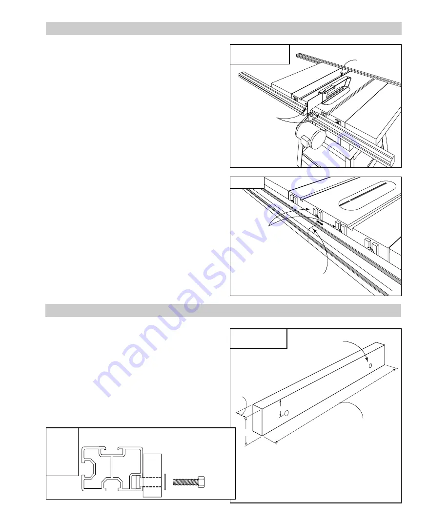
If you wish to add a 

3

4

" thick table board between the right

hand extension wing of your table saw and the TS III base
mount assembly, begin by making two of the wooden
supports like the one shown in 

 .  For the length of

the support, measure the distance between your extension
wing and the base mount assembly.  Loosely attach the
fasteners through the holes in the supports.  Remove the
base assembly from your saw, then slide the square nuts
into the inside T-slots on each rail, 

 .  Cut a table

board to fit and screw to the supports.  The oversize holes
in the support should allow range for positioning the table
board flush with your table saw top.

If, after reinstalling the blade guard and tilting the motor, you
find that the rear rail interferes with the blade guard, you
must add the two remaining rail mounting brackets and split
the rear rail to provide the necessary clearance as shown in

 .  Begin by removing the base mount assembly.

Loosen the bolts that secure the rear rail to the existing
brackets and slide the rail off.  Reinstall the blade guard,
then locate the positions for the additional rail mounting
brackets on either side of the blade guard.  The mounting
brackets should be placed as close as possible to the blade
guard, but before drilling the mounting holes, make sure to
check the positions for clearance when the blade is tilted to
45°.  When you have found the mounting bracket locations,
drill a 

3

8

"diameter hole in the center of each position.  The

center of the hole should be about 1

1

8

" below the table top.

Remove blade guard, then using 

3

8

–16 x 1

1

2

" hex bolts,

nuts and washers, attach the extra mounting brackets
loosely in place.   Install the rail bolts as shown in 

  on

page 4, then slide the rear rail back into position.  Tighten
all rail mounting bolts, then tighten the two bolts that secure
the brackets to your table saw.  Use a hacksaw to make a
cut through the rear rail about halfway between the two
additional rail mounting brackets.  Loosen the bolts that
secure the rails to the brackets and slide the rails to create
an opening large enough to reinstall the blade guard.  See

 . Again, tilt the blade to 45° to check for clearance.

Once the rail positions are established, sand or file the cut
ends of the rails to remove any sharp edges.  Tighten the
bolts that secure the rails, then repeat the alignment and
calibrations starting with 

  on page 7.

BLADE GUARD ADJUSTMENTS

FIG. 26

Rear rail modification

Two rail mounting 

brackets are used

on each side of

blade guard to

provide support for

split rear rail

modification

Blade guard

FIG. 27

Cut through rear rail 

between additional mounting 

brackets and separate the two rail 

sections to create opening for blade guard

EXTENSION TABLE

FIG. 28

Table board support

Note: Above dimensions are

for a 

3

4

" thick table board.

Adjust hole position for

different table board thickness

DETAIL

28A

Attaching

table

board

support

1

5

32

3

4

"

3

8

" dia. hole

For length, measure

distance between

extension wing and

base assembly

Fasteners required:  

(4) 

1

4

– 20 x 1" hex bolts

(4) 

1

4

" flat washers

(4) 

1

4

– 20 square nuts

1

3

4

INCRA TS III Owner’s Manual

11

Additional rail

mounting brackets

Summary of Contents for TS III

Page 1: ...er the base mount unit These two assemblies are covered fully by this owner s manual The third package contains the INCRA Jig Ultra 32 Read all of this TS III owner s manual and pages 2 3 6 7 18 and 19 of the Ultra owner s manual In just about an hour or so you are going to be operating one of the most exciting new tools in today s woodshops Your table saw will undergo a transformation and what wa...

Page 2: ...sure that the blade is fully stationary before changing the setting on any part of the INCRA TS III Always keep both hands behind the fence when moving the INCRA TS III to a new setting Before making a cut always make sure that the carriage clamp is fully engaged and that the rail hook thumbscrew is securely tightened Use appropriate safety devices Keep hands clear of the saw blade Always use a pu...

Page 3: ... 6 each 1 4 flat washer 4 each 3 8 16 dual pilot rectangular nut 4 each 3 8 16 x 3 4 clamping knob 4 each 3 8 16 x 1 2 hex bolt 6 each 10 32 x 1 2 phillips pan head screw 6 each 10 flat washer 6 each 10 32 hex nut 4 each 3 16 thick nylon washer 4 each 3 8 16 x 3 8 socket head set screw ULTRA Mounting Hardware Pack INCRA TS III Owner s Manual 3 Note Each hardware pack is labeled and bagged separate...

Page 4: ... the Rail Hardware Pack Add a 3 8 flat washer to each of 4 3 8 16 x 3 4 hex bolts Place the bolts through the holes in the mounting brackets and loosely attach the 3 8 16 rectangular nuts See above Slide rails onto mounting brackets and tighten bolts Carefully slide the rails onto the mounting brackets so that the rectangular nuts are captured in the T slot on the bottom of the rail shows the corr...

Page 5: ...saw as shown in Push the rail against the short vertical leg on the mounting bracket and tighten the bolts that hold the rail in place See below 4 5 Short vertical leg FIG 5 Tighten mounting bracket bolts Base clamp Table saw top Mounting bracket bolt Mounting bracket is at correct level when base clamp touches table top FIG 6 Set final rail position Rails should extend 7 beyond left hand extensio...

Page 6: ...the panel end and the vertical surface on the base clamp as shown in and tighten the screws Set aside the remaining fasteners from the Base Mount Fence Glide Hardware Pack for use in and on page 8 Remove endcaps from base support panel See at right BASE MOUNT ASSEMBLY Attach glide pads to underside of base clamps Peel the adhesive backing from the glide pad and adhere to the base clamp as shown in...

Page 7: ...amps as necessary to align the panel parallel to the miter slot Tighten the four base clamping knobs then tighten all eight screws that secure the base clamps to the base support panel Replace the base support panel end caps FIG 14 Set final base assembly position Base clamp 36 First Slide base assembly to 36 from saw blade and tighten all 4 clamping knobs 3 16 hex tool INCRA TS III Owner s Manual...

Page 8: ...s you tighten the screws Engage anti lift rail hooks Lock the carriage clamp then turn the black thumbscrew on the front fence glide counterclockwise to lower the rail hook into the T slot on the rail Look into the T slot as you lower the hook When the hook passes the lip on the T slot slide the black thumbscrew toward the table saw to position the hook under the lip See Now turn the thumbscrew cl...

Page 9: ... the micro adjust mode as described on page 7 of your Ultra s owner s manual and micro adjust the fence forward until it kisses the saw blade Release the micro adjust lever and lock the carriage in place Note After micro adjusting re zero the scale on the micro adjust knob by rotating the scale not the knob to return to zero under the micro cursor Set scale position With the Ultra still locked at ...

Page 10: ...m the saw blade Place the Ultra in micro adjust mode and micro adjust the fence forward until it kisses the saw blade After micro adjusting release the micro adjust lever and lock the carriage in place Whenever you return the Ultra to operation on the right side of the blade remember to micro adjust the fence back to a zero reading on the micro adjust scale Set scale and stop positions Slide the e...

Page 11: ...he center of the hole should be about 11 8 below the table top Remove blade guard then using 3 8 16 x 11 2 hex bolts nuts and washers attach the extra mounting brackets loosely in place Install the rail bolts as shown in on page 4 then slide the rear rail back into position Tighten all rail mounting bolts then tighten the two bolts that secure the brackets to your table saw Use a hacksaw to make a...

Page 12: ...years of virtually maintenance free operation In fact just keeping your TS III clean is all you need to do to keep the tool in top shape Occasionally remove the carriage from the base and brush or blow out any sawdust or debris that may have accumulated Use a toothbrush to clean the teeth on the INCRA racks on both the carriage and the base A light application of paste wax to the top of the rails ...

Reviews: