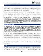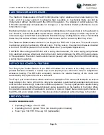
PART #22018-DH - High-Resolution Positioner
Page 21
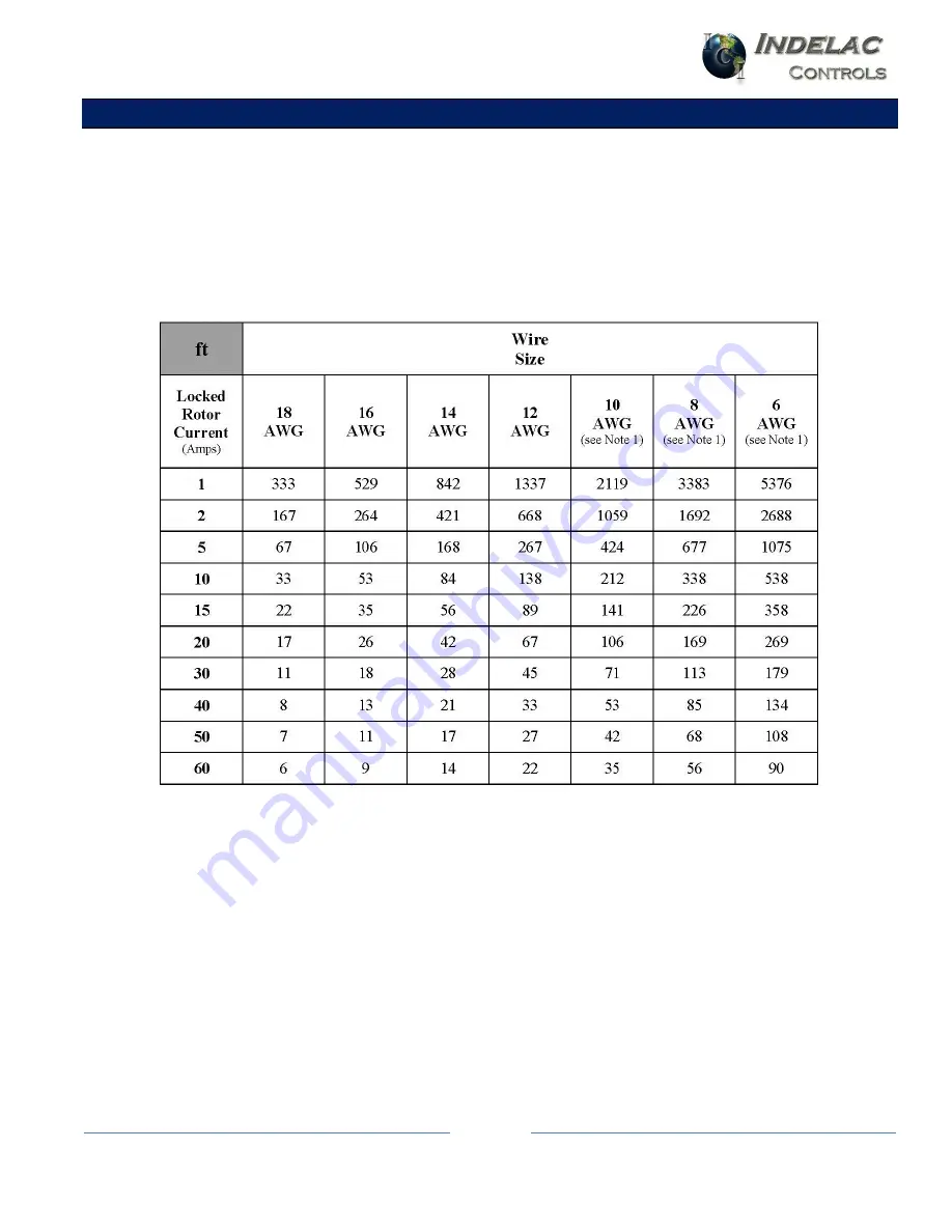
WIRING TABLE:
The table below shows the maximum recommended distance (in linear feet) between the power
source and the DHC-400 unit. The maximum distance is limited by the wire size used and the locked
rotor current of the motor. The surge limiting feature along with an appropriate motor current trip
setting can reduce wire size and power source requirements to a minimum (see TRIP SETTING).
The wire distance is calculated for a maximum voltage drop of 1VDC with 20% of the locked rotor
current, and assumes that the full load running current is less than that. All signal wires on the DHC-
400 should be connected with wire sizes ranging from 22 to 18 AWG.
NOTES
1) The DHC-400 terminal strip will not accept wire sizes larger than 12 AWG. Use a short run of 12
AWG from the DHC-400 to an auxiliary terminal block when larger wire is needed.
2) If the motor is located some distance from the DHC-400, add this length to the overall wire length;
be sure to use an appropriate wire size to the motor.
3) When multiple actuators are powered by a common set of wires, use the sum of all the motor
currents when determining wire size.
Summary of Contents for 22018-DH
Page 1: ......
Page 3: ...PART 22018 DH High Resolution Positioner Page 3 BOARD OUTLINE...
Page 17: ...PART 22018 DH High Resolution Positioner Page 17 WIRING DIAGRAMS Output Configurations...
Page 18: ...PART 22018 DH High Resolution Positioner Page 18 WIRING DIAGRAMS Input Configurations...
Page 19: ...PART 22018 DH High Resolution Positioner Page 19 WIRING DIAGRAMS Special Applications...
Page 20: ...PART 22018 DH High Resolution Positioner Page 20 WIRING DIAGRAMS Special Applications...


