PART #22018-DH - High-Resolution Positioner
Page 5
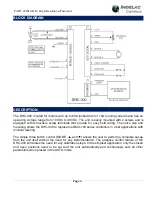
POWER / SIGNAL: (J2):
The positive terminal of the DC power source is connected to pin 1 while the negative terminal
connects to pin 2. When the DHC-400 is mounted to a metal bracket or directly to the actuator case,
pin 3 provides a terminal for an earth ground connection to the actuator body. In applications where
the actuator body is non-metallic or is electrically isolated from earth ground, pin 3 must be
connected to earth ground to prevent static voltage buildups.
Transferring DC power can be inefficient, therefore care should be taken to use appropriate wire
sizes. The size wire required depends on the locked rotor motor current and the length of wire to be
used. See the Wire Table for more information.
An appropriate command signal, either 0-5V, 0-10V, 1-5V, 2-10V, or 4-20mA, should be connected
to pin 5 (as shown in the Block Diagram) while using pin 4 as the return signal ground. See Wiring
Diagrams, Input Configurations, for wiring details. The DHC-400 must be configured for the type of
command signal that is to be used (see COMMAND TYPE).
Pin 6 of J2 provides an auxiliary +5V output which can be used to connect a command
potentiometer. By connecting one end of a potentiometer to pin 6, the other end to pin 4, and the
wiper to pin 5, a local control knob can be implemented. Pin 4 will also need to be connected to pin
2 (BAT NEG) for this application.
ACTUATOR (J1):
The actuator motor and feedback potentiometer are connected to J1 as shown in the Block Diagram.
The feedback potentiometer wiper must be connected to pin 5, while one end is connected to pin 4
and the other end to pin 6. The Polarity Detection feature of the DHC-400 automatically determines
which polarity to apply to the motor based on where the open and closed positions are set; this
feature also eliminates the need to rewire the unit for direct or reverse acting applications.
Many actuators include limit switches that are used to turn off the motor when the extreme ends of
travel have been reached. Limit switches should be wired to pins 6, 7, and 8 as shown in the Block
Diagram. If limit switches are not used, pins 7 and 8 must be connected to pin 6 (note, if pins 7 and
8 are not connected to pin 6, the DHC-400 will not be able to control the motor outputs).
When the ▲ and ▼ buttons are used to control the actuator, the ▲ button will connect pin 4
(MOTOR 1) to BAT POS (J2-1) and pin 5 (MOTOR 2) to BAT NEG (J2-2) as long as pin 7 (LIMIT
SW1) is connected to pin 6
(LIMIT COMMON). Likewise, the ▼ button will connect pin 5 to BAT
POS and pin 4 to BAT NEG as long as pin 8 (LIMIT SW2) is connected to LIMIT COMMON.
Since pins 4 and 5 are alternately connected to BAT POS (J2-1) and BAT NEG (J2-2), care should
be taken not to connect the motor output pins to any other terminals. See MANUAL/FB POT CAL
for more details.
The DHC-400 provides a dynamic braking feature that can eliminate the need for a separate brake.
When the DHC-400 turns off the motor outputs, pins 4 and 5 are internally connected to the BAT
NEG pin (J2-2); this has the effect of shorting the motor leads together, thus braking the motor
Summary of Contents for 22018-DH
Page 1: ......
Page 3: ...PART 22018 DH High Resolution Positioner Page 3 BOARD OUTLINE...
Page 17: ...PART 22018 DH High Resolution Positioner Page 17 WIRING DIAGRAMS Output Configurations...
Page 18: ...PART 22018 DH High Resolution Positioner Page 18 WIRING DIAGRAMS Input Configurations...
Page 19: ...PART 22018 DH High Resolution Positioner Page 19 WIRING DIAGRAMS Special Applications...
Page 20: ...PART 22018 DH High Resolution Positioner Page 20 WIRING DIAGRAMS Special Applications...


