background image

10 of 13

Service Manual UK

Indesit

Company

English

SERVICING & DISMANTLING INSTRUCTIONS

Important Notes for Guidance:

Before commencing any work refer to the Safety Notes and Safety Precaution at the beginning of this 
manual.

Caution:

When carrying out the following procedures care must be taken to protect the appliance and 
customers property, especially if the appliance is moved or laid down. Where it is necessary to 
lay the appliance down, it must be cleared of food and furniture. It must not be tilted or 
supported against a wall or similar structure.

The Grip Mat, Part Number C00222890 (5700072), must always be used as directed when laying 
an appliance on its back to reduce appliance movement.

A.

Freezer Door

1.

Lay down the appliance on its back.

2.

Unscrew, remove and retain the bottom hinge.

3.

Slightly open the freezer door and slide downwards to remove.

B.

Fridge Door

1.

Remove the freezer door as in A1 to A3.

2.

Remove centre hinge and spacer if fitted. Slightly open the fridge door and slide downwards to remove.

C.

Lamp

1.

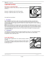
Squeeze to unclip the lamp cover located at the rear of the controls box
(see Fig. 3).

2.

Unscrew and remove lamp; the replacement lamp must be of the same rating 
as the power range indicated on the cover.

D.

Thermostat Control Box

1.

Remove the blanking cap (where applicable) and the fixing screw (located in 
front of the thermostat control knob).

2.

Slide the control box forward to disengage from locating post.

3.

Disconnect the lamp wiring.

4.

Disconnect the thermostat wiring.

E.

Thermostat

1.

Remove the thermostat control box as in D1, D2 and D4.

2.

Release the thermostat fixing nut and remove the thermostat from the control box.

3.

Withdraw the thermostat phial from the phial ducting.

F.

Console Facia Panel

1.

Remove the freezer door as in A1 and A3.

2.

Remove the fridge door as in B1 and B2.

3.

Remove the two screws securing the console panel to the cabinet. Do not remove the upper hinge pin.

4.

Pull the console panel forward and remove.

G.

Door Reversal - Refer to Page 11

H.

Door Seal Replacement - Refer to Page 12

Fig. 3

Summary of Contents for CA55KUK

Page 1: ...B Registered in London 106725 Service Information INDESIT FREESTANDING FRIDGE FREEZERS Models Comm Covered Code CA55UK 69937 CA55KUK 74471 CA55SUK 75733 Energy Band A Models CAA55UK 77736 CAA55KUK 777...

Page 2: ...ss power tools are forbidden within the storage area working area and vehicles used to transport Isobutane 9 The carrying case for the scales and refrigerant must display a red flammability label Part...

Page 3: ...y be dispensed to the appliance from the 1kg net aluminium canister placed in an upright position on the weighing scales provided 4 All used canisters must be a returned as scrap and therefore left ou...

Page 4: ...Fuse A Max 15 w Total Gross Bruto Brut Compr Kompr Syst R 134 a kg 0 090 Gross Bruto Brut 340 Net Util Utile Gross Bruto Brut Freez Capac Poder de Cong 75 Made in 13918 Test P S I Pressure HIGH 235 LO...

Page 5: ...l be frosted similarly it will be wet following compressor switch off This is known as Wet Wall Design The control box is located inside the top right side of the fridge compartment The control box co...

Page 6: ...0 kg CA55 NCAA55 Models 2011 Regulation 3 0 kg CAA55 Models 2011 Regulation Climate Class N SN ST 10 C to 32 C CA55 Models SN N ST T 10 C to 43 C CAA55 NCAA55 Models Operating Voltage 220 240 V All Mo...

Page 7: ...Other Dedicated 17 hours Conservation Time CA55 Models 2011 Regulation 14 hours Conservation Time 2011 Regulation CAA55 NCAA55 13 hours 17 hours Defrosting Fridge Automatic Freezer Manual Compressor M...

Page 8: ...s by number and or position There is only one adjustable foot TEMPERATURE REGULATING Knob SHELVES GLASS COVER FRUIT and VEGETABLE bins FREEZER and STORAGE compartment STORAGE compartments Levelling FO...

Page 9: ...freezing fresh food The use of the Low Ambient Fast Freeze switch may encourage excessive ice to form on the fridge evaporator This is normal while the switch is in the ON position once the switch is...

Page 10: ...Remove centre hinge and spacer if fitted Slightly open the fridge door and slide downwards to remove C Lamp 1 Squeeze to unclip the lamp cover located at the rear of the controls box see Fig 3 2 Unscr...

Page 11: ...t from the top right hand and refit into the hole in the left hand side Refit the top front cover 7 Use a thin blunt instrument to remove the top and bottom hinge bushes and blanking plugs from the do...

Page 12: ...section retained by the liner 3 Each section can then be withdrawn from the liner using snipe nosed pliers and pulling Where the seal is particularly tight in the liner slot it might be helpful to ea...

Page 13: ...desit Company English THEORETICAL WIRING DIAGRAM R S COMPRESSOR RFA52 5407275wd pdf if fitted CAPACITOR LIGHT LIGHT SWITCH HEATER FAST FREEZE SWITCH 4 3 6 PTC THERMOSTAT BROWN BROWN BLACK BROWN BLACK...

Reviews: