background image

O

PERA

T

I

ON

G

B

14

Service Manual

Ne

w


E

lectronic Cold Platform 2005

Edition

2005.03.25

Language

E

nglish

I

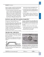
n alarm status the appliance forces operation utilising specific On / Off parameters that control the tem-

perature in the freezer compartment at specific values depending on the type of alarm. To reset the alarm
and restore normal operation, the appliance must be set to LOG

I

CAL OFF (freezer knob set to minimum).

Control of freezer compartment temperature is continuous during operation of the appliance, by means of
the freezer air temperature sensor; this control will proceed even if the appliance is in one of the two
available alarm conditions. 

I

n the event of a freezer air sensor fault, the alarms will no longer be displayed.

Temperature control is not performed for a time parameterised in the EEPROM memory to prevent false
alarms both during the testing process and at the time of power-on immediately after the appliance has
been purchased.
Temperature control and alarm signalling are managed by means of three thresholds: Check Threshold
(the control strategy becomes more intensive when this threshold is exceeded); Threshold A1: when ex-
ceeded, alarm A1 is activated; Threshold A2: when exceeded, alarm A2 is activated. The values of the three
thresholds are parameterised in the EEPROM memory.

I

f the control temperature exceeds the Check Threshold but does not exceed the A1 Alarm threshold, a

delay time T1 is activated (parameterised in the EEPROM) before performing the next control, to prevent
the generation of alarm signals when the placement of large quantities of warm food in the freezer compart-
ment near the freezer air sensor causes unreliable transient temperature readings. At the same time an-
other time interval T2 is activated (parameterised on the EEPROM) after which, if the temperature is con-
stantly maintained between the Check Threshold and the Alarm A1 Threshold, alarm A1 is forced because
the persistence of a temperature in this range for this period of time is anyway a symptom of faulty operation
and constitutes a risk for the correct preservation of the food.
At the time of activation of alarm A1 also a time interval T3 is activated (parameterised in the EEPROM)
after which, if an alarm reset has not been executed, alarm A2 is forced, since in the situation of alarm A1
the freezer compartment is set to a temperature that may not be the same as the temperature selected by
the user. This time interval is reset also when power is restored after a mains power failure.

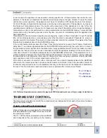
TH

E

RMOSTAT CONTROL.

The temperature adjustments in both the compartments are independent from each other and set individu-
ally by the relative knobs.

Freezer Compartment Adjustment:

  8°C

-6°C

  2°C

T1 = 2 1/2 Hours

T2 = 24 Hours

T1 = 120 Hours

N. B.: The time and temperature values sho

w

n in this graph are 

EE

PROM parameters and as such they are subject to modification

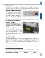
Freezer temperature is managed by the PCB utilising
the value detected by the freezer air sensor to switch
the compressor on/off.
The On / Off threshold is detected by the EEPROM
and it depends on the user setting.on the interface.

Summary of Contents for New electronic cold platform 2005

Page 1: ...iability for possi ble errors or omissions no part of this document can be reproduced used or copied without written permission or without being authorised by the terms of a contract clause Service Ma...

Page 2: ...upporting document for technical personnel It contains a description of the various product types the general operating principle and indications concerning assistance Technical personnel should anywa...

Page 3: ...S 30 38 4 WIRING DIAGRAMS 39 47 Main PCB circuit diagram 39 41 Sensors diagram 42 46 Freezer wiring diagram 47 5 ASSISTANCE 48 63 Demo Mode 48 Auto Test Testing Running in 48 Faults and solutions 50 5...

Page 4: ...models T Colour Teak S Colour Silver X Colour Stainless Steel I Isobutane Gas for classes A B C NF Full no frost W Grilles P Playzone L Lock G Graffiti Final letters EU F etc Intended markets 1 PRODUC...

Page 5: ...latform 2005 Edition 2005 03 25 Language English 1 2 INTERFACE No Frost Fridge freezer and Electronic Thermostat Double Door Basic Electronic Static Fridge Freezer Evolution Electronic Static Fridge F...

Page 6: ...ic Cold Platform 2005 Edition 2005 03 25 Language English 1 3 ENERGY LABEL Energy Label for products BAN or TAN Class A energy label Energy Label for products BAAN orTAAN Class A energy label Indesit...

Page 7: ...the knob clockwise away from the Minimum position appli ance OFF Turn the knob counterclockwise to the Minimum position to switch off the appliance TEMPERATURE ADJUSTMENT ture The refrigerator compart...

Page 8: ...witched off even in the presence of a cool ing demand 3 Pause after defrost at the end of the defrost cy cle the compressor observes a protection time parameterised in the EEPROM so that the water for...

Page 9: ...s and the EEPROM memory For faults of this type there are various alternative operating modes that can be activated to allow the appliance to continue to function normally Normal operation of the appl...

Page 10: ...set to Minimum To switch the appliance on turn the freezer knob clockwise away from the Minimum position To switch it off turn the knob counterclockwise to the Minimum position All active functions ar...

Page 11: ...ime parameterised in the EEPROM memory to run continuously to obtain the maximum cooling capacity in the refrigerator compartment The SUPER COOL function cannot be activated if either of the two freez...

Page 12: ...utomatically when the maximum time has elapsed 24 or 48 hours or in the case of 24 h mode once a given temperature has been reached and maintained for a time interval parameterised in the EEPROM memor...

Page 13: ...isplayed on the freezer temperature display At the same time an audible signal is emitted by the beeper during both alarm modes This function allows storage of food with the lowest possible power cons...

Page 14: ...n the EEPROM before performing the next control to prevent the generation of alarm signals when the placement of large quantities of warm food in the freezer compart ment near the freezer air sensor c...

Page 15: ...on strategy is observed only after the product has been operating continuously for a number of hours defined in the memory This facilitates the execution of factory tests Long periods of activity If t...

Page 16: ...ng This occurs in the event that the fridge door is open In order to check that the refrigerator fan is functioning correctly door closed conditions must be simulated by applying a magnet Fridge Lamp...

Page 17: ...partment will be switched off while setting the freezer knob to minimum switches off the entire appliance The appliance is Off when the freezer compartment knob 6 is set to Minimum To switch the appli...

Page 18: ...s restored completing the remaining hours unless a tempera ture alarm occurs in this interval SUPER COOL FUNCTION When the SUPER COOL function is inhibited the appliance returns to the setting that wa...

Page 19: ...gle beep and the appliance will resume normal operation The HOLIDAY function cannot be activated when ECO FUNCTION This function allows storage of food with the lowest possible power consumption while...

Page 20: ...eset the alarm and restore normal operation the appliance must be set to LOGICAL OFF freezer knob set to minimum The beeper can be muted by opening and closing the refrigerator door When alarm status...

Page 21: ...faulty operation and constitutes a risk for the correct preservation of the food At the time of activation of alarm A1 also a time interval T3 is activated parameterised in the EEPROM after which if a...

Page 22: ...t least one of the previous conditions is no longer detected or because the condition persists for a time greater than the relative parameter set in the EEPROM memory LOADS MANAGEMENT Compressor Opera...

Page 23: ...ycle the number of hours is calculated that the compressor needs to run before starting the next defrost cycle This calculation is performed on the basis of the duration of the defrost cycle that has...

Page 24: ...evaporator coil is coming out of the drain tube FREEZER FAN The purpose of the freezer fan is to distribute the cold air produced by the evaporator coil inside the freezer compartment The freezer fan...

Page 25: ...mper is closed even in the presence of a cooling demand from the refrigerator compartment and when the compressor is running The damper is opened again only when the fridge door is closed To check ope...

Page 26: ...and a fan located in the freezer compartment behind the com partments partition Fig 2 partments partition Fig 2 Fig 3 The cold air that flows through the evaporator coil is routed to the Refrigerator...

Page 27: ...Cold Platform 2005 Edition 2005 03 25 Language English The cold air is delivered from the vents serving the refrigerator compartment fig 4 and the freezer com partment fig 5 Fig 5 Fig 4 Blue Delivery...

Page 28: ...eated after the thermal exchange is cooled and dehumidified by the coil The ice that accumulates on the coil is periodically removed by means of a system of heating elements and the result ing melt wa...

Page 29: ...to the required temperature values which are regulated by means of suitable thermostat control Function of the solenoid valve The solenoid valve is controlled in such a way as to route the cold refrig...

Page 30: ...ew Electronic Cold Platform 2005 Edition 2005 03 25 Language English 3 COMPONENTS ELECTRONIC THERMOSTAT NO FROST FRIDGE FREEZER Control Panel Thermostat PCB Multiflow unit Mechanical damper Fridge com...

Page 31: ...latform 2005 Edition 2005 03 25 Language English 1 2 3 4 5 6 7 Rear Components Key 1 Compressor Compartment 2 Compressor 3 Water Bowl 4 Filter 5 Delivery Tube 6 Return Tube 7 Capillary tube Light Fixt...

Page 32: ...lectronic Cold Platform 2005 Edition 2005 03 25 Language English BASICELECTRONICSTATICFRIDGE FREEZEROREVOLUTIONMODEL Basic control panel Evolution control panel Freezer Air Sensor Freezer Evaporator F...

Page 33: ...nic Cold Platform 2005 Edition 2005 03 25 Language English Fridge fan evolution model only and lamp holder Ice container and drawer Main PCB strip Display Interface PCB Evolution Base Main PCB Cover 1...

Page 34: ...nual New Electronic Cold Platform 2005 Edition 2005 03 25 Language English 1 2 3 4 5 6 7 8 Rear Components Key 1 Compressor Compartment 2 Compressor 3 Water Bowl 4 Filter 5 Main PCB 6 Delivery Tube 7...

Page 35: ...Electronic Cold Platform 2005 Edition 2005 03 25 Language English ELECTRONIC THERMOSTAT DOUBLE DOOR NO FROST Thermostat PCB Control Panel Freezer compartment fan Freezer Air Sensor Freezer compartment...

Page 36: ...MPONENTS GB 36 Service Manual New Electronic Cold Platform 2005 Edition 2005 03 25 Language English Fridge compartment Mechanical damper Damper Cover Mechanical damper sensor Light Fixture Multiflow u...

Page 37: ...ice Manual New Electronic Cold Platform 2005 Edition 2005 03 25 Language English 1 2 3 4 5 6 7 Rear Components Key 1 Compressor Compartment 2 Compressor 3 Water Bowl 4 Filter 5 Delivery Tube 6 Return...

Page 38: ...W 3 1 16 Control techniques Control is executed by transmitting the entire mains voltage HEATING ELEMENTS Load type resistive Electrical specifications datasheet Voltage V 220V 240 Frequency Hz 50 dr...

Page 39: ...W IRING D IAGRAMS GB 39 Service Manual New Electronic Cold Platform 2005 Edition 2005 03 25 Language English 4 WIRING DIAGRAMS...

Page 40: ...W IRING D IAGRAMS GB 40 Service Manual New Electronic Cold Platform 2005 Edition 2005 03 25 Language English...

Page 41: ...W IRING D IAGRAMS GB 41 Service Manual New Electronic Cold Platform 2005 Edition 2005 03 25 Language English...

Page 42: ...MS GB 42 Service Manual New Electronic Cold Platform 2005 Edition 2005 03 25 Language English SENSOR DIAGRAM 1 Used in Fridge Freezer Appliance H 1750 Fridge Freezer Appliance H 1850 Fridge Freezer Ap...

Page 43: ...IRING D IAGRAMS GB 43 Service Manual New Electronic Cold Platform 2005 Edition 2005 03 25 Language English SENSOR DIAGRAM 2 Used in NF Fridge Freezer Appliance H 1875 NF Fridge Freezer Appliance H 200...

Page 44: ...W IRING D IAGRAMS GB 44 Service Manual New Electronic Cold Platform 2005 Edition 2005 03 25 Language English Used in Double Door Appliance H 1750 Double Door Appliance H 1850 SENSOR DIAGRAM 3...

Page 45: ...W IRING D IAGRAMS GB 45 Service Manual New Electronic Cold Platform 2005 Edition 2005 03 25 Language English SENSOR DIAGRAM 4 Used in All products with mini PCB in control Panel...

Page 46: ...W IRING D IAGRAMS GB 46 Service Manual New Electronic Cold Platform 2005 Edition 2005 03 25 Language English SENSOR DIAGRAM 5 Used in Fridge freezer appliances with special compartment...

Page 47: ...onic Cold Platform 2005 Edition 2005 03 25 Language English FREEZER COMPARTMENT FRONT SIDE ELECTRICALWIRING DIAGRAM Used in all No Frost appliances R1 Coil heating element R2 Drip tray heating element...

Page 48: ...feature an Autotest procedure that is able to assess correct operation of various loads and sensors Electronic Thermostat Autotest Activation of the Autotest procedure for this appliance must be perf...

Page 49: ...for these appliances must be performed by executing the following proce dure 1 Turn the Fridge knob to the minimum position compartment OFF 2 Turn the Freezer knob to the minimum position appliance OF...

Page 50: ...accordance with the following table the LEDs remain lit as long as the fault persists Fault Indication Led1 Led2 Led3 F01 Off Flashing Off F02 On Flashing Off F03 Off Flashing On F04 On Flashing On F0...

Page 51: ...damper connection to the foam embed ded connector behind the multiflow unit Renew electronic damper Renew PCB Check efficiency of contacts on PCB connector J6 Check condition by checking for impedance...

Page 52: ...it with your hand where possible and checking the change in the impedance value Renew PCB Check efficiency of contacts of PCB connector J11 Check NTC sensor ensuring that the impedance value read on p...

Page 53: ...rrectly positioned Condensate collection bowl not in contact with compressor Faulty thermostat Incorrectly positioned thermostat Unsuitable installation on electrical Klixon Door fails to close proper...

Page 54: ...the re frigerator 2 Unscrew the two screws one for each side re sponsible for securing the control panel 3 Pull the control panel pressure fit and remove the temperature control knob 4 Disconnect the...

Page 55: ...lish 3 Remove plastic cover from light fixture 4 Unscrew the screws at base of multiflow unit and screw inside lamp holder 5 Pull multiflow unit causing it to slide downwards by a couple of centimetre...

Page 56: ...English Removing Fridge Freezer freezer compartment components 1 Remove the drawer from the freezer compartment 2 Unscrew the five cover screws 3 Insert a slotted screwdriver into the cover upper hole...

Page 57: ...t fan terminals Removing double door appliance freezer compartment components 2 Insert a slotted screwdriver in both sides of the cover and detach 3 Pull cover 4 Unscrew the two screws holding the int...

Page 58: ...r refit simply apply pressure in the necessary direction To remove the cover of the freezer compartment air return vent simply in sert a slotted screwdriver in the outer part and press upwards taking...

Page 59: ...using it to slide down wards taking care not to damage the damper sensor 4 Disconnect the lamps power terminal 5 Remove the damper temperature adjustment knob 6 Unscrewthetwoscrewsthatsecuretheplastic...

Page 60: ...Manual New Electronic Cold Platform 2005 Edition 2005 03 25 Language English Removing the water collection bowl 1 Use a screwdriver to detach the clips on both sides 2 After detaching the clips remove...

Page 61: ...inals BASIC ELECTRONIC STATIC FRIDGE FREEZER OR EVOLUTION MODEL 2 Unscrew the two screws one on each side re sponsible for securing the control panel 4 Press the fixing tabs and remove the PCB Removin...

Page 62: ...e English Removing the Lamp holder 1 Slide the plastic cover to the rear 3 Unscrew the screws on both sides of lamp holder 2 Remove cover 4 Disconnect the terminal board Removing the Main PCB 1 Undo t...

Page 63: ...lectronic Cold Platform 2005 Edition 2005 03 25 Language English Removing the water collection bowl 1 Use a screwdriver to detach the clips on both sides 4 Remove PCB from cover 2 After detaching the...

Page 64: ...E XPLODED VIEWS GB 64 Service Manual New Electronic Cold Platform 2005 Edition 2005 03 25 Language English 6 EXPLODED VIEWS DIGITAL ELECTRONIC STATIC FRIDGE FREEZER...

Page 65: ...E XPLODED VIEWS GB 65 Service Manual New Electronic Cold Platform 2005 Edition 2005 03 25 Language English DIGITAL ELECTRONIC STATIC FRIDGE FREEZER...

Page 66: ...E XPLODED VIEWS GB 66 Service Manual New Electronic Cold Platform 2005 Edition 2005 03 25 Language English DIGITAL ELECTRONIC STATIC FRIDGE FREEZER...

Page 67: ...E XPLODED VIEWS GB 67 Service Manual New Electronic Cold Platform 2005 Edition 2005 03 25 Language English DIGITAL ELECTRONIC STATIC FRIDGE FREEZER...

Page 68: ...E XPLODED VIEWS GB 68 Service Manual New Electronic Cold Platform 2005 Edition 2005 03 25 Language English DIGITAL ELECTRONIC STATIC FRIDGE FREEZER...

Page 69: ...E XPLODED VIEWS GB 69 Service Manual New Electronic Cold Platform 2005 Edition 2005 03 25 Language English DIGITAL ELECTRONIC STATIC FRIDGE FREEZER...

Page 70: ...E XPLODED VIEWS GB 70 Service Manual New Electronic Cold Platform 2005 Edition 2005 03 25 Language English DIGITAL ELECTRONIC STATIC FRIDGE FREEZER...

Page 71: ...E XPLODED VIEWS GB 71 Service Manual New Electronic Cold Platform 2005 Edition 2005 03 25 Language English DIGITAL ELECTRONIC STATIC FRIDGE FREEZER...

Page 72: ...43 70 1753 04 Temperatures Impedance degC Ohms 75 1480 91 80 1256 39 85 1070 31 90 915 42 95 785 96 100 677 30 105 585 75 110 508 32 115 442 59 120 386 60 125 338 74 130 297 70 135 262 38 140 231 91...

Page 73: ......
Page 74: ...ompany viale Aristide Merloni 47 60044 Fabriano Italy tel 39 0732 66 11 telex 560196 fax 39 0732 66 2954 www indesitcompany com Service Manual New Electronic Cold Platform 2005 Edition 2005 03 25 Lang...

Reviews: