A
SS
I
ST
ANCE
G
B
50
Service Manual
Ne
w
E
lectronic Cold Platform 2005
Edition
2005.03.25
Language
E
nglish
1
2
3
5
4
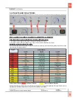
5.2. FAULTS AND SOLUTIONS:
Key: 1 = L
E
D 1; 2 = L
E
D 2; 3 = L
E
D 3; 4 = DIGIT FR; 4 = DIGIT FZ
Fig.2
Fig.1
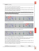
The fault type can be signalled in various different
w
ays:
1. by means of the LEDs in the case of the basic interface (see fig.1)
2. by means of the LEDs and digits in the case of the Evolution interface (see fig.2)
Reading of faults sho
w
n by L
E
Ds
The control panel LEDs illuminate to show the fault in accordance with the following table (the LEDs remain
lit as long as the fault persists).
Fault
Indication
Led1
Led2
Led3
F01
Off
Flashing
Off
F02
On
Flashing
Off
F03
Off
Flashing
On
F04
On
Flashing
On
F05
Flashing
Flashing
On
F06
On
Flashing
Flashing
F07
Off
Flashing
Flashing
F08
Flashing
Flashing
Off
F09
Flashing
Flashing
Flashing
F12
Off
Off
On
F14
On
Off
On
F21
On
On
Flashing
F22
Flashing
On
On
F23
Flashing
On
Flashing
F24
Off
On
Flashing
F25
On
Off
Flashing
L
E
D Fault Table
Critical Faults
Non-critical Faults
The first 9 faults are critical: the user will have to call service to repair the appliance; the next 8 faults can be
checked by a technical engineer by means of the autotest procedure.
Summary of Contents for New electronic cold platform 2005
Page 73: ......


