background image


RuralConnect

®

 Gen3


TV White Space Radio 

User Manual 

V1.0 

Summary of Contents for Carlson RuralConnect Gen3

Page 1: ...RuralConnect Gen3 TV White Space Radio User Manual V1 0...

Page 2: ...responsible for technical assistance for all other system components Local product support is provided by Indigo Broadband in South Africa The first point of contact should always be via their support...

Page 3: ...be lethal When selecting an installation site keep safety and performance in mind Make sure there are no power lines anywhere where possible contact can be made Carefully check the distance to any pow...

Page 4: ...ccur in a particular installation If this equipment does cause harmful interference to radio or television reception which can be determined by turning the equipment off and on the user is encouraged...

Page 5: ...nections 16 3 2 2 Power Network Connections 16 Registration Information 16 3 3 1 Base and CPE Registration Details 16 3 3 2 Owner Operator Information 17 Software Configuration 17 3 4 1 Finding the Ba...

Page 6: ...nnect Antennas 45 6 4 1 Base Station Sector Antenna 45 6 4 2 Client Station Log Periodic Antenna 45 Weatherproofing RF Connections 47 Antenna Alignment 48 Interference Solutions 49 Surge Protection 49...

Page 7: ...r Interface Ethernet Port Setup Screen 33 Figure 24 Base Station User Interface Ethernet Port Bridge Routing 34 Figure 25 Base Station User Interface Ethernet Port VLAN Settings 35 Figure 26 User Inte...

Page 8: ...yright 2020 Carlson Wireless Technologies Inc All Rights Reserved Figure 47 Step 3 Covering Rubber Tape with Electrical Tape 47 Figure 48 Base Station RF Surge Protector Diagrams 50 Figure 49 CPE RF S...

Page 9: ...ll Rights Reserved Tables Table 1 Sector Antenna Specifications 45 Table 2 Log Periodic Directional Antenna Specifications 46 Table 3 High Value Base Station RF Surge Protector Specifications 50 Table...

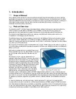
Page 10: ...MHz or 32 Mbps 8 MHz over the air Both units are powered via an external Power over Ethernet POE injector The Base Station consumes up to 25 Watts while the CPE consumes up to 8 Watts The RuralConnect...

Page 11: ...Hz channel bandwidth The system is fully compliant with ETSI EN 301 598 regulations To prevent exceeding an authorized power limit the radio includes an internal RF sensor that reads the RF power outp...

Page 12: ...optimal electrical conductivity it is best to use the largest diameter ground wire the ground connectors will accept We recommend using a solid copper wire no smaller than eight gauge It is required...

Page 13: ...s strongly recommended that you use only Carlson approved cables Discuss your cabling options with your Carlson Sales Representative Carlson carries professional grade RF coax cables that provide grea...

Page 14: ...by the factory prior to shipment After a radio has been enrolled and connected to the Internet it will attempt to register with the WSDB and request channel allocations Via software unit registration...

Page 15: ...h your new RuralConnect system To access the Knowledge Base open your web browser and navigate to www carlsonwireless com Hover your cursor over Support and click the Knowledge Base link To access the...

Page 16: ...pplied to each unit to From the IN port of the Base Station POE injector connect your LAN Internet connection Connect your first computer to Local Area Network LAN to which the Base Station is connect...

Page 17: ...specify a different operator contact a lead technician that will be responsible for the system hereon If your networks are operated by an organization that does not own the equipment be sure the owne...

Page 18: ...a DHCP server running by default If the attached computer is configured to obtain an IP address via DHCP it will automatically obtain an IP address from the CPE The default IP address of the CPE is 19...

Page 19: ...dmin and click the Log in button 3 4 3 Home Page This page includes an overview of your TV White Space network including some configuration and status details System Status Note the up time This time...

Page 20: ...Screen Location Antenna Height Manual Override If the unit is not GPS enabled or no satellites are within range click the GPS Details button at the bottom of the Radio Manager Screen Under Location Ma...

Page 21: ...contact details of the parties who own the equipment and those responsible for its operation At the bottom of the Screen click the Contact Details button and fill in every field After you complete a...

Page 22: ...lue next to Center Frequency MHz Browse to the Home page to view the status of each sector and any connected CPEs Test Internet Connection Open a web browser and navigate to a webpage of your choice Y...

Page 23: ...With a local PC log into local router and look under the connected devices list to find the BS IP address Look for picasso name or MAC address beginning with 70 B3 D5 x x Also make sure local area net...

Page 24: ...up to the Radio Manager Screen Check the manager status does it say Channels Allocated Set up Radios Make sure that Mac address is different for each sector Unless you want shared access make the SSID...

Page 25: ...tion User Interface CPE Management Flowchart Go to the CPE Management screen If you have aThe system will recognize Add New CPE s and enter details such as DHCP or set IP address for each one desired...

Page 26: ...There are three sections At the top is a block containing system information The host name and system location may be changed by clicking on them and typing new values There is also a button that all...

Page 27: ...ing a tick in the check box on the left and clicking the Delete Users button The password of a user may be changed here by clicking the Change button in the Password column An account is allocated a s...

Page 28: ...e following Awaiting GPS The system is waiting for the GPS module to report a valid location for the base station Check the location block described below or the GPS Details page Disabled The Radio Ma...

Page 29: ...ally indicate channel list available if the communication was successful Finally there is the Configuration block at the bottom In this block each radio card s configuration can be set If Automatic Ch...

Page 30: ...t shows details of the CPEs that are connected to the base station and allows their configuration both before and after they connect Figure 21 Base Station User Interface CPE Management The CPE Manage...

Page 31: ...k box and clicking CPE Details can access the same panel for an already configured CPE A CPE can be deleted by ticking its select check box and clicking the Delete CPE button Confirmation is requested...

Page 32: ...earned This mode is agnostic to whether the traffic is IP version 4 or IP version 6 The source and destination must still agree on which IP version they are using The only configuration required in th...

Page 33: ...In addition to the Port Configuration function there are buttons at the bottom of the page that provide access to other Ethernet related Screens 4 4 1 Bridge Routing Table The base station contains a...

Page 34: ...4 Base Station User Interface Ethernet Port Bridge Routing 4 4 2 VLAN Details The base station has basic support for 802 1q VLAN tagging This sub page allows the VLAN configuration of the Ethernet and...

Page 35: ...yright 2020 Carlson Wireless Technologies Inc All Rights Reserved Figure 25 Base Station User Interface Ethernet Port VLAN Settings 4 4 3 Interface status The Interface Status sub page indicates the c...

Page 36: ...ase station while the uplink is performed by the CPE Figure 27 Base Station User Interface UL DL Traffic Shaping The first step in configuring traffic shaping is via the Traffic Shaping page Here the...

Page 37: ...New Device on this page will create a new shaping device whose MAC address will default to the CPE MAC address If the CPE is operating in NAT router mode this is the only device shaping can work with...

Page 38: ...pplication Software The Application Software page reports the current version of software running on the unit The base station can store two versions of the application one of which is currently runni...

Page 39: ...er be aware that the CPE information is only transferred from the CPE to the base station roughly once every 10 seconds so higher sample rates for these parameters make little sense Clicking the Downl...

Page 40: ...the browser and the self signed certificate The default username and password is the same as for the base station Username is Admin and password is Admin Once you successfully log in you will arrive a...

Page 41: ...ptions 5 2 1 DHCP Server The CPE provides a DHCP server that can be configured to supply IP addresses to devices on the LAN in NAT Router and Router modes This feature is disabled in Bridge mode the c...

Page 42: ...CPE User Interface DHCP Server Screen Traffic Shaping The traffic shaping system is controlled by the base station as described in section 4 5 The traffic shaping page on the CPE shows the devices th...

Page 43: ...e also on this page The main ones are the SSID and Passphrase which must match the base station configuration Part of the acquisition sequence the CPE goes through is a survey of available channels Th...

Page 44: ...characteristics of signals in the UHF band good connections are generally possible even if there is a non line of sight path to the Base Station Once a link to the Base Station is established clients...

Page 45: ...e U bolts around the bottom section of the antenna and place the mount saddles over them the curved side facing the antenna b Keeping the mount plate perpendicular to the antenna slide the U bolts int...

Page 46: ...idth 3 dB 28 degrees Maximum Mast Diameter 60 mm Antenna Connector F type female 75 Ohms Frequency Range 470 862 MHz Gain 10 11 dBi Weight Dimensions 1kg 38cm x 35cm Table 2 Log Periodic Directional A...

Page 47: ...tape and extend 15mm beyond the F Type male connector This step is highly recommended as it will make removal of the weatherproofing faster easier and cleaner Tightly wrap the connectors with two laye...

Page 48: ...to be With the wide beam width of the log periodic antenna rated performance can be achieved at 28 degrees while best performance can be achieved at 5 degrees Receive Signal Level Indicator RSSI Ligh...

Page 49: ...he offenders Use RF trap filter s to isolate interference from specific channels If you are not a professional installer consult with the dealer service provider or other experienced technician Surge...

Page 50: ...the body of the surge protector The other end of the ground wire must tie into the tower ground system or other verified earth ground You must seal in line lightning protectors from moisture which can...

Page 51: ...an optional plastic enclosure is available Carlson Part Number 640 6550 Operating Voltage Data 5V POE 48V Clamping Voltage 7 5V Data Pins 1 2 3 6 70V POE Pins 4 5 7 8 Max Surge Discharge Current 10KA...

Page 52: ...missions RF Rx Signal Maximum 16 dBm with full linearity Channel Access Method CSMA Carrier Sensing Multiple Access User Ports 10 100 1000 Mbps Ethernet Ethernet Cable Connection required Cat 6 or 6a...

Page 53: ...ect mishandling misapplication alteration modification lightning power line surge introduction of sand dust humidity and or liquids or service by anyone other than a Carlson Factory Service Center or...

Page 54: ...atellite System GPS GLONASS Galileo BeiDou GUI Graphical User Interface IP Internet Protocol LAN Local Area Network NAT Network Address Translation OFDM Orthogonal Frequency Division Multiplexing OMC...

Page 55: ...thernet A set of computer networking technologies for local area networks LANs IP Internet Protocol Provides for transmitting blocks of data between hosts identified by fixed length addresses LAN Loca...

Page 56: ...system Carlson does not authorize untrained and or unqualified personnel to work on the system without the supervision of a qualified technician Spectrum Registration ICASA information regarding Whit...

Page 57: ...esult in warranty voiding equipment damage personal injury fines and or the loss of applicable licenses Information provided here is strictly for reference purposes OSHA Guidelines Part 1910 Occupatio...

Reviews: