RuralConnect® Gen3 User Manual V1.0
Page | 51 of 57
Copyright
©
2020 Carlson Wireless Technologies, Inc. All Rights Reserved.
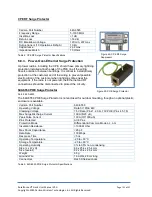
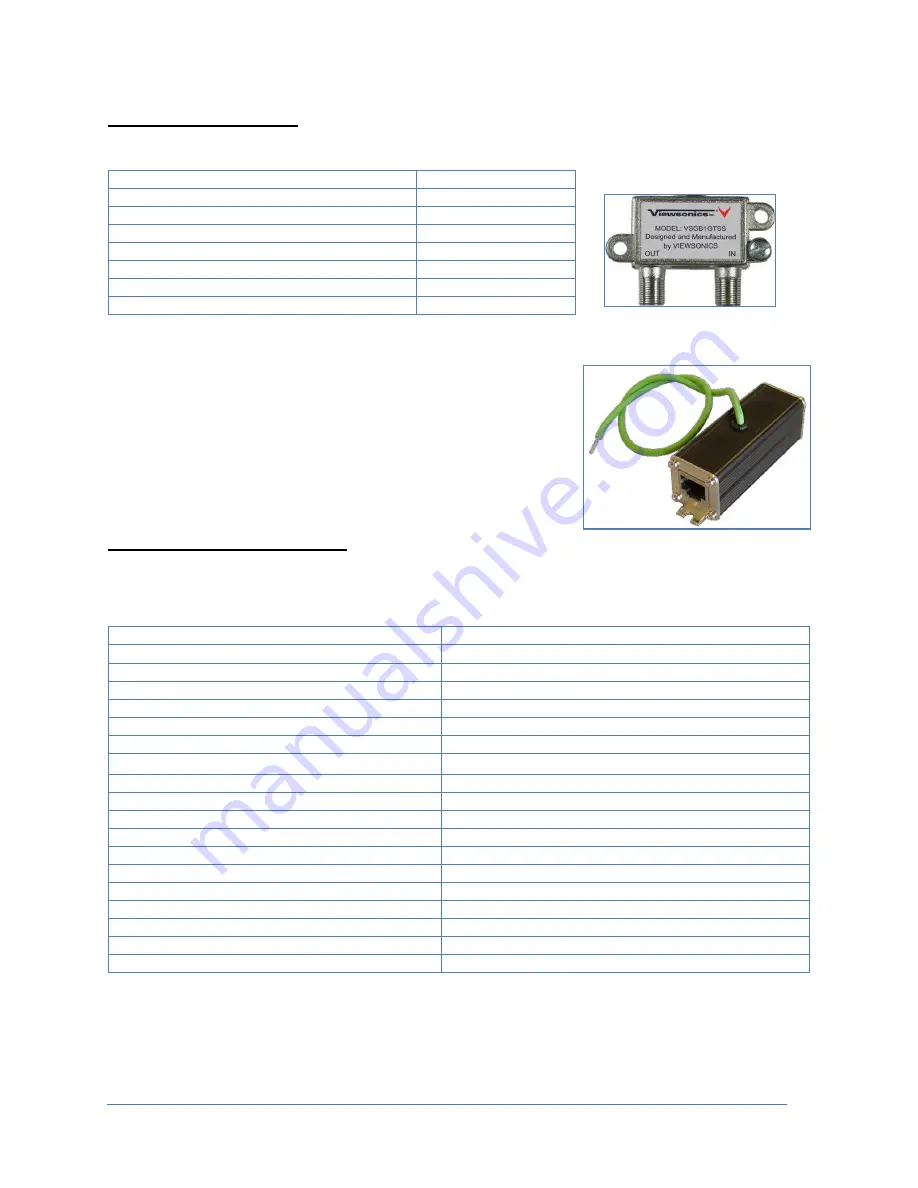
CPE RF Surge Protector
Table 4: CPE RF Surge Protector Specifications
6.8.3. Power-Over-Ethernet Surge Protection
Up tower radios, including the CPE, should have primary lightning
protection installed at both ends of the POE line if the wiring
travels outside or between buildings. It is critical to install primary
protection at the customer end of the wiring to prevent possible
electrocution of the customer when lightning strikes near the
equipment. If the radio is not powered, the Ethernet and RF
connections should be disconnected to protect the circuitry.
640-6550 POE Surge Protector
Part #: 650-6550
The 640-6550 POE Surge Protector is not enclosed for outdoor mounting, though an optional plastic
enclosure is available.
Carlson Part Number
640-6550
Operating Voltage
Data 5V; POE 48V
Clamping Voltage
7.5V Data (Pins 1,2,3,6), 70V POE (Pins 4,5,7,8)
Max Surge Discharge Current
10KA (8/20 µS)
Peak Pulse Current
100A (10/1000 µS)
Pins Protected
All 8 Pins
Protection Mode
Differential & Common Mode L-L, L-G
Insulation Resistance
>1000 M Ohm
Max Shunt Capacitance
<25 pF
Data Rate
100 Mbps
Response Time
<5 ns
Operating Temperature
-20 to +60°C
Storage Temperature
-20 to +80°C
Operating Humidity
0% to 95% non-condensing
Size (L x W x H)
68 x 25.4 x 25.4 mm
Size (overall)
82 x 25.4 x 25.4 mm
Weight
68 g
Ground Wire
16 AWG, 26 cm long
Connectors
RJ45 Shielded Jacks
Table 5: 640-6550 POE Surge Protector Specifications
Carlson Part Number
640-6565
Frequency Range
5-1000 MHz
Insertion Loss
<1 dB
Return Loss
>18 dB
DC Breakdown Voltage
120 min, 297 max
Surge Current (10 Operations 8/20µS)
10 kA
Capacitance
2 pF max
Impedance Match
75 Ohms
Figure 49: CPE RF Surge
Suppressor
Figure 50: POE Surge Protector

