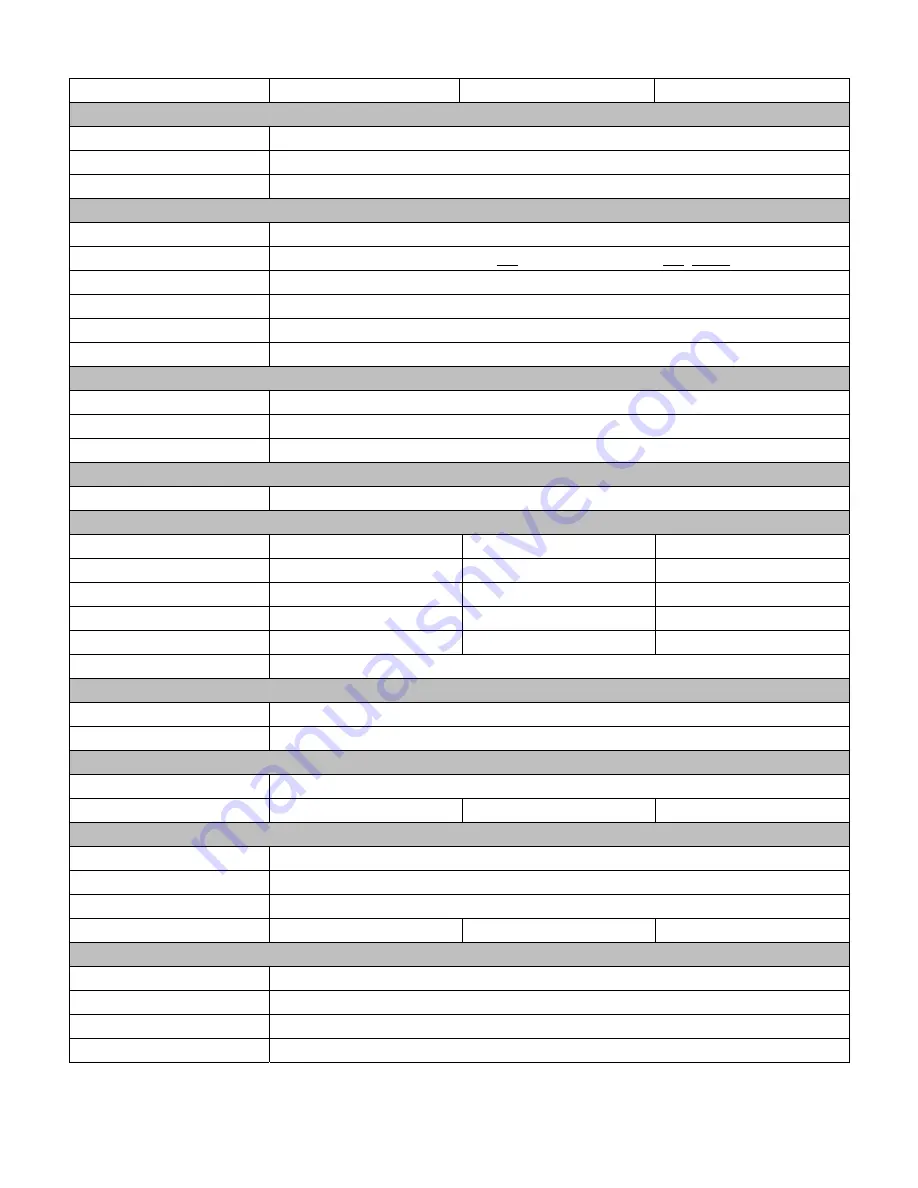
1.1 Specifications
Model IMP-A151[G]T
IMP-A171[G]T
IMP-A191T
System
CPU Intel
®
Atom™ Cedar View D2550 1.8GHz Dual Core Processor
System chipset
Intel NM 10 Express
System memory
2 x 204-pin DDR3 SO-DIMM 800/1066MHz, up to 4GB
I/O Ports
USB
4 x USB 2.0 type A
Serial / Parallel
1 x RS-232, 1 x RS-232/422/485 and 1 x RS-422/485 (default)
Audio
1 x MIC-in, 1 x Line-out
External display
1 x VGA
LAN
2 x GbE
Other
1 x 2 pin remote power switch
Storage Space
HDD
1 x 320 GB SATA HDD
Card reader
1 x Externally accessible CompactFlash slot
Supported OS
Windows XP Pro, Windows Standard Embedded 7 (32bit)
Expansion
Expansion slots
1 x PCI slot
Display
Display type
15” TFT-LCD
17” TFT-LCD
19” TFT-LCD
Max. resolution
1024x768
1280x1024
1280x1024
Max. color
262K
16.7M 16.7M
Luminance (cd/m
2
) 40 350 350 2
View angle
160° / 160°
170° / 170°
170° / 160°
Backlight lifetime
50,000 hrs
Touch Screen
Type
Analog resistive on ‘T’ models, GFG on ‘GT’ models
Light transmission
80% for ‘T’ models / 90% for ‘GT’ models
Power
Input voltage
DC 9~32V
Power consumption
33.2W
47.6W 48.1W
Mechanical
Construction
Steel front and cover
IP rating
IP65 front panel
Mounting
Panel mount / VESA 75
Dimensions (w x h x d)
410 x 310 x 94.8mm
439 x 348 x 94.3mm
484 x 400 x 94.3mm
Environmental
Operating temperature
0~50°C
Storage temperature
-20~60°C
Storage humidity
10 to 90% @ 40°C, non- condensing
Certification
CE / FCC Class A
IMP-A1x1
User Manual
1
Summary of Contents for IMP-A151[G]T
Page 1: ...Industrial Panel PCs IMP A1x1 Series User Manual...
Page 4: ......
Page 21: ...Dimensions of the IMP A151 Panel Cut out Chapter 4 Dimension drawings 17 IMP A1x1 User Manual...
Page 22: ...Dimensions of the IMP A17 Panel Cut out Chapter 4 Dimension drawings 18 1 IMP A1x1 User Manual...
Page 23: ...Dimensions of the IMP A191 Panel Cut out Chapter 4 Dimension drawings 19 IMP A1x1 User Manual...
Page 24: ...This page intentionally left blank...
Page 25: ...This page intentionally left blank...
Page 26: ...Indumicro com Edition 2 0...

![Preview for 1 page of Indumicro IMP-A151[G]T User Manual](http://thumbs.mh-extra.com/thumbs/indumicro/imp-a151-g-t/imp-a151-g-t_user-manual_2054086-01.webp)
![Preview for 2 page of Indumicro IMP-A151[G]T User Manual](http://thumbs.mh-extra.com/thumbs/indumicro/imp-a151-g-t/imp-a151-g-t_user-manual_2054086-02.webp)
![Preview for 3 page of Indumicro IMP-A151[G]T User Manual](http://thumbs.mh-extra.com/thumbs/indumicro/imp-a151-g-t/imp-a151-g-t_user-manual_2054086-03.webp)
![Preview for 4 page of Indumicro IMP-A151[G]T User Manual](http://thumbs.mh-extra.com/thumbs/indumicro/imp-a151-g-t/imp-a151-g-t_user-manual_2054086-04.webp)
![Preview for 5 page of Indumicro IMP-A151[G]T User Manual](http://thumbs.mh-extra.com/thumbs/indumicro/imp-a151-g-t/imp-a151-g-t_user-manual_2054086-05.webp)
![Preview for 6 page of Indumicro IMP-A151[G]T User Manual](http://thumbs.mh-extra.com/thumbs/indumicro/imp-a151-g-t/imp-a151-g-t_user-manual_2054086-06.webp)
![Preview for 7 page of Indumicro IMP-A151[G]T User Manual](http://thumbs.mh-extra.com/thumbs/indumicro/imp-a151-g-t/imp-a151-g-t_user-manual_2054086-07.webp)
![Preview for 8 page of Indumicro IMP-A151[G]T User Manual](http://thumbs.mh-extra.com/thumbs/indumicro/imp-a151-g-t/imp-a151-g-t_user-manual_2054086-08.webp)
![Preview for 9 page of Indumicro IMP-A151[G]T User Manual](http://thumbs.mh-extra.com/thumbs/indumicro/imp-a151-g-t/imp-a151-g-t_user-manual_2054086-09.webp)
![Preview for 10 page of Indumicro IMP-A151[G]T User Manual](http://thumbs.mh-extra.com/thumbs/indumicro/imp-a151-g-t/imp-a151-g-t_user-manual_2054086-10.webp)
![Preview for 11 page of Indumicro IMP-A151[G]T User Manual](http://thumbs.mh-extra.com/thumbs/indumicro/imp-a151-g-t/imp-a151-g-t_user-manual_2054086-11.webp)
![Preview for 12 page of Indumicro IMP-A151[G]T User Manual](http://thumbs.mh-extra.com/thumbs/indumicro/imp-a151-g-t/imp-a151-g-t_user-manual_2054086-12.webp)
![Preview for 13 page of Indumicro IMP-A151[G]T User Manual](http://thumbs.mh-extra.com/thumbs/indumicro/imp-a151-g-t/imp-a151-g-t_user-manual_2054086-13.webp)
![Preview for 14 page of Indumicro IMP-A151[G]T User Manual](http://thumbs.mh-extra.com/thumbs/indumicro/imp-a151-g-t/imp-a151-g-t_user-manual_2054086-14.webp)
![Preview for 15 page of Indumicro IMP-A151[G]T User Manual](http://thumbs.mh-extra.com/thumbs/indumicro/imp-a151-g-t/imp-a151-g-t_user-manual_2054086-15.webp)
![Preview for 16 page of Indumicro IMP-A151[G]T User Manual](http://thumbs.mh-extra.com/thumbs/indumicro/imp-a151-g-t/imp-a151-g-t_user-manual_2054086-16.webp)
![Preview for 17 page of Indumicro IMP-A151[G]T User Manual](http://thumbs.mh-extra.com/thumbs/indumicro/imp-a151-g-t/imp-a151-g-t_user-manual_2054086-17.webp)
![Preview for 18 page of Indumicro IMP-A151[G]T User Manual](http://thumbs.mh-extra.com/thumbs/indumicro/imp-a151-g-t/imp-a151-g-t_user-manual_2054086-18.webp)
![Preview for 19 page of Indumicro IMP-A151[G]T User Manual](http://thumbs.mh-extra.com/thumbs/indumicro/imp-a151-g-t/imp-a151-g-t_user-manual_2054086-19.webp)
![Preview for 20 page of Indumicro IMP-A151[G]T User Manual](http://thumbs.mh-extra.com/thumbs/indumicro/imp-a151-g-t/imp-a151-g-t_user-manual_2054086-20.webp)


