background image

10 - ENG

200-2927

MAINTENANCE

NOTE:   

Once the motor pulley has been moved from its factory  


set location, the grooves of the flywheel and pulley must  


be aligned to within 1/16” to prevent excessive belt wear.


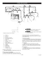
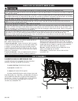
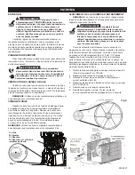
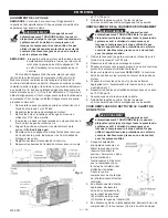
To check pulley alignment, remove the belt guard and place 

a straightedge (see 

A

) against the pump flywheel (see 

B

) (See 

Fig. 9

). Measure and record the distance from the straightedge to 

the edge of the drive belt at point C. Then measure the distance 

from the straightedge to the edge of the drive belt again at points 

D and E. Both distances should be the same as at point C. If D 

or E are different from C, there is a misalignment which must 

be corrected before the compressor is run. To correct a pulley 

misalignment, use the following procedure.
1.  Remove the front of the belt guard by removing the screws  


using a Torx T25 bit.

2.  Loosen the motor mounting bolts.

3.  Remove the 2 screws and lock washers from the hub using a  


7/16” wrench.

4.  Insert the screws into the threaded holes on the hub and    


tighten to pull hub away from sheave, remove screws.

5.  Align the motor pulley with the pump flywheel (C-D-E must  


be equal ).

6.  Replace hub by aligning non-threaded holes in hub to holes  


in sheave. Insert screws and lock washers and tighten.

7.  Adjust the proper belt tension.

8.  Retighten the motor mounting bolts to 130-180 in.-lbs.

9.  Reinstall the belt guard. All moving parts must be guarded.

This unit starts automatically.  


  ALWAYS shut off the main power disconnect, and  

  bleed all pressure from the system before servicing  

  the compressor, and when the compressor is not in  


use. Do not use the unit with the shrouds or belt    


guard removed. Serious injury could occur from    


contact with moving parts.

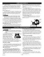
1.  Remove the front of the belt guard by removing the screws  


using a Torx T25 bit. 

2.  Loosen the motor mounting bolts.

3.  Shift the motor towards the pump to the point where the belts  


can be easily removed and installed.

4.  Remove and replace belts. NOTE: The belts must be  


centered over the grooves on the flywheel and motor pulley.

5.  Shift the motor back to the point where the correct deflection  


exists (see “Drive Belt Tension Adjustment”).

6.  Retighten the motor mounting bolts to 130-180 in.-lbs.

7.  Check to ensure that the tension remained correct.

8.  Reinstall the belt guard. All moving parts must be guarded.

This unit starts automatically.  


  ALWAYS shut off the main power disconnect, and  

  bleed all pressure from the system before servicing  

  the compressor, and when the compressor is not in  


use. Do not use the unit with the shrouds or belt    


guard removed. Serious injury could occur from    


contact with moving parts.

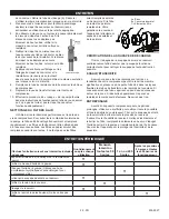
1.  Shut OFF the main power  


disconnect. Relieve all  


the air pressure from the tank  


(refer to “Shutdown” in  


Operating Instructions).  


Make sure the compressor  


has cooled down before  

 servicing.

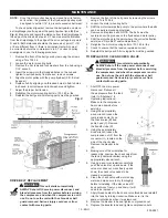
2.  Using the appropriately  


sized wrench, loosen the  


compression nuts (A) on  


the check valve (B) and  


pump head (C). Remove  


the transfer tube (D).


3.  Using the appropriately  


sized wrench, loosen the  


compression nut (F) from the  


connector (G), located on the  


side of the check valve.  


Remove the bleeder tube  

 (E).

4.  Making note of the orientation for  


reassembly, unscrew the check valve from  


the tank (counterclockwise) using the    


appropriately sized wrench. 

5.  Using a pencil or screwdriver, carefully    


push the valve disc up and down. If the    


valve disc does not move freely up and    


down, the check valve needs to be  


cleaned or replaced.

6.   Clean the check valve with warm soapy   


water and make sure to dry thoroughly    


before reinstalling. If the disc valve still    


does not move freely up and down, it will  


need to be replaced. 

7.  Apply thread sealant to the check valve threads and reinstall  


into the tank by turning clockwise. Make sure it is the  


same orientation as when it was removed. 

8.  Replace the bleeder tube and tighten compression nut.

9.  Replace the transfer tube and tighten compression nuts.

Fig. 9

TO REPLACE OR CLEAN CHECK VALVE

WARNING:

DRIVE BELT REPLACEMENT

WARNING:

Summary of Contents for IV5076055

Page 1: ...manuel avant d utiliser l outil Toute d rogation aux instructions contenues dans ce manuel peut entra ner l annulation de la garantie causer des blessures et ou des dommages mat riels Le fabricant NE...

Page 2: ...ny manner will void the warranty If tank develops a leak replace it immediately with a new tank or replace the entire compressor RISK OF ELECTRICAL SHOCK Never use an electric air compressor outdoors...

Page 3: ...compressed air distribution lines RISK OF FIRE Unattended operation of this compressor could result in personal injury or property damage To reduce the risk of fire do not allow the compressor to oper...

Page 4: ...oil lubed compressors oil can leak or spill and could result in fire or breathing hazard Oil leaks will damage paint carpet or other surfaces in vehicles or trailers Always place the compressor on a p...

Page 5: ...the power panel and use a longer air hose or distribution line to reach the usage area b The flywheel side of the compressor must be at least 12 inches 31 cm from any wall or obstruction in a clean w...

Page 6: ...k not pressure in the air line Install an air regulator in the drop line for each tool to regulate air pressure to that tool Never exceed the maximum pressure rating of the tool Air lubrication Instal...

Page 7: ...OPS senses both temperature and current providing more complete motor overload protection than a magnetic starter which senses only current If TOPS senses an overload condition it will automatically s...

Page 8: ...the tank petcock see D 4 Turn ON the main power disconnect switch Turn the pressure switch to the AUTO position see B The pump will start filling the tank with air When the air pressure in the tank re...

Page 9: ...starts automatically ALWAYS shut off the main power disconnect and bleed all pressure from the system before servicing the compressor and when the compressor is not in use Do not use the unit with the...

Page 10: ...belts can be easily removed and installed 4 Remove and replace belts NOTE The belts must be centered over the grooves on the flywheel and motor pulley 5 Shift the motor back to the point where the cor...

Page 11: ...e filter becomes filled with paint it should be replaced Direct exposure to dirty conditions or painting areas will void your warranty Pull the tank safety valve daily to ensure that it is operating p...

Page 12: ...and flywheel Check alignment Low oil level in pump crankcase Keep oil at proper level at all times Excess carbon on valves or top of piston Contact a qualified service center Oil in discharge air Worn...

Page 13: ...nnulera la garantie Si une fuite est observ e sur le r servoir le remplacer imm diatement par un nouveau r servoir ou remplacer le compresseur au complet RISQUE DE CHOC LECTRIQUE Ne jamais utiliser un...

Page 14: ...ier galvanis pour propulser l air comprim RISQUE D INCENDIE Le fonctionnement sans surveillance du compresseur pourrait entra ner des blessures corporelles ou des dommages la propri t Ne pas laisser l...

Page 15: ...istribuer correctement l huile Tous les pieds doivent tre soutenus et des cales doivent tre plac es aux endroits n cessaires avant la fixation au sol Fixez tous les pieds au sol Il est galement recomm...

Page 16: ...d une ligne de distribution pour atteindre la zone d utilisation b Le compresseur doit tre situ au moins 30 cm de tout mur ou obstacle dans un endroit propre et bien ventil afin d assurer une circula...

Page 17: ...te d air Installer un r gulateur d air dans la conduite de drainage de chaque outil pour r guler la pression d air de cet outil Ne d passez jamais la limite de pression de l outil Lubrification de l a...

Page 18: ...OMMANDES DU COMPRESSEUR AVERTISSEMENT Veillez ce que toutes les s curit s et protections soient install es avant d appuyer sur l interrupteur de remise en marche Le TOPS d tecte la temp rature et l in...

Page 19: ...rsque l air comprim est utilis le manocontacteur red marrera le moteur automatiquement afin d envoyer davantage d air comprim dans le r servoir AVERTISSEMENT El moteur lectrico y la bomba del compreso...

Page 20: ...lacer le bouchon de remplissage de l huile Ne remplissez jamais au dessus du niveau ou underfill la pompe REMARQUE Utilisez une huile completement synthetique et sans detergent pour compresseur d air...

Page 21: ...s en mouvement doivent tre prot g es par une s curit Cet appareil se met automatiquement TOUJOURS arr ter le pouvoir disjoncteur principal et purger toute la pression du syst me avant l entretien du c...

Page 22: ...le Votre garantie sera annul e si l appareil est directement expos des salet s et de la peinture Tirer sur la bague de la soupape de s ret du r servoir quotidiennement afin d assurer que la soupape f...

Page 23: ...Cognement de la pompe Poulie du moteur ou volant motoeur desserr Resserrez la poulie et le volant moteur V rifiez l alignement Niveau d huile trop bas dans le carter de la pompe Maintenez le niveau d...

Page 24: ...re invalidar la garant a Si detecta un escape en el dep sito reempl celo inmediatamente con un nuevo dep sito o reemplace todo el compresor RIESGO DE DESCARGA EL CTRICA Nunca utilice un compresor el c...

Page 25: ...nes personales o da os materiales No utilice mangueras de pl stico o pvc para aire comprimido Use solo mangueras y conectores de acero galvanizado para l neas de distribuci n de aire comprimido RIESGO...

Page 26: ...e gotear o derramarse y ocasionar un peligro de incendio o causar problemas de respiraci n El goteo de aceite podr a da ar la pintura las alfombrillas u otras superficies de veh culos o remolques Depo...

Page 27: ...el compresor cerca del panel de alimentaci n y el uso de una manguera de aire m s largo o l nea de distribuci n para alcanzar el rea de uso b El lado del volante del compresor se debe encontrar como...

Page 28: ...de aire en la l nea de ca da para cada herramienta a fin de regular la presi n de aire hacia dicha herramienta Nunca debe sobrepasar la presi n nominal m xima de la herramienta Lubricaci n de aire Ins...

Page 29: ...agado Man metro del tanque vea D Este man metro mide la presi n del aire almacenado en el tanque No es ajustable por el operador y no indica la presi n de la l nea CONTROLES DEL COMPRESOR REQUISITOS D...

Page 30: ...aire y disminuir el nivel de presi n en el dep sito el interruptor de presi n volver a arrancar el motor y el bomba comenzar a llenar neuvamente el dep sito ADVERTENCIA La bomba genera altas temperatu...

Page 31: ...exceso NOTA Utilice un aceite completamente sintetico y sin detergente para compresor de aire NOTA El ajuste de la tensi n de la correa de transmisi n y la alineaci n de la polea se realizan al mismo...

Page 32: ...la correa Todas las piezas m viles deben quedar protegidas Esta unidad arranca autom ticamente SIEMPRE apague el compresor quite el enchufe de la toma de corriente y purgue toda la presi n del sistema...

Page 33: ...diciones de suciedad y zonas en las que est n pintando anular n su garant a Tire de la v lvula de seguridad del dep sito todos los d as para asegurarse de que la v lvula funciona adecuadamente y para...

Page 34: ...ificado Golpeteo de la bomba del compresor Polea del motor o volante del compresor suelto Vuelva a ajustar la polea y el volante Verifique la alineaci n Bajo nivel de aceite en el c rter de la bomba M...

Page 35: ...200 2927 35 200 2927 NOTES...

Page 36: ...Conservez votre re u et ce manuel pour r f rence ult rieure Quand vous avez besoin des services de l usine s il vous pla t contactez au centre d entretien autoris le plus proche ou composez simplemen...

Reviews: